ECU Remap Guide – EDC16CP35. BMW E90 335D 286HP – Stage 3
01.04.2025This short guide provides step-by-step instructions for a Stage 3 remap of the BMW 335D 286HP with the EDC16CP35 ECU. It is designed for enthusiasts looking to unlock more engine potential and perform the remap themselves. I have simplified the process to make it as clear as possible.
If you have any questions, feel free to message me directly on Facebook Messenger: https://www.facebook.com/aliantauto.
Before You Start
If you are unfamiliar with key diesel engine components—such as the turbocharger, turbocharger controller, and sensors like MAF, MAP, and FRP—or the common rail fuel injection system, and cannot dedicate at least 2-3 hours a day for 1-3 months to learning the fundamentals and testing your attempts, this guide may not be suitable for you.
For complete beginners, it might be better to read the articles in the General section before going through this guide.
What You Need for a Successful Stage 3 Remap
- Car: BMW 335D 286HP with an EDC16CP35 ECU.
- Diagnostic Tool: Used to log real-time data after each modification.
- Examples: Testo, Bimmerlink, Deep OBD.
- ECU Programming Tool: Required to read the original file and write modified files.
- Examples: MPPS, Galletto v54, Alientech Kess V3.
- Battery Stabilizer: It is recommended to maintain stable voltage during the reading and writing files.
- Example: GYSFLASH 100.12 HF.
- WinOLS Software: A specialized tool for modifying ECU memory content, making it easier to find and edit maps.
Key Guidelines
Before modifying any factory settings, you must evaluate the vehicle’s current condition by logging essential parameters such as: Mass airflow, Turbo pressure, Rail pressure, Injector corrections, Fuel mixture, etc. For diesel engines, logging should be done in 3rd or 4th gear, from 1200 to 4500 RPM, at 100% throttle. Use specialized software and interfaces compatible with your car brand. If you detect deviations from factory parameters, resolve them before making any modifications to the ECU file!
When you are a beginner and lack experience, I advise you to change parameters in small increments and monitor how they affect the vehicle through logging. If at any point you do not know or are unsure of the consequences of certain changes, it is best to do nothing and continue searching for information!
By following these guidelines, you can successfully complete a Stage 3 remap and enhance your vehicle’s performance while minimizing risks.
Example Stage 3. Includes the following modifications to the vehicle:
- Turbocharger Upgrade – Turbosystems Stage 2 BMW M57D30TÜ2
- Intake Upgrade
- Intercooler Upgrade – Wagner Competition Intercooler Kit EVO3
- Valve Springs Upgrade
- High-Pressure Pump Upgrade – HPFP CP3 R90
- High-Pressure Regulator Upgrade – DRV30
- High-Pressure Sensor Upgrade – 50D 2700bar
- Custom Downpipe and Exhaust System – 90mm
- EGR deleted, DPF and VSA removed
- Transmission Software Upgrade – xHP Stage 3
Here, I will describe the main maps required for this specific Stage 3, which includes increasing the power to around 480HP and 950NM. I provide brief explanations for each type of map, while all other maps are uploaded to the respective album on my Facebook page.
If you have any questions or would like me to send you a package with all maps (Mappack.kp), please send a private message to my Facebook Messenger: https://www.facebook.com/aliantauto.
1. Driver Wish maps
These maps define the required torque based on engine RPM and throttle pedal position in percentages (%). Adjustments are made according to the driver’s preferences, with the highest desired NM value always set at 100% throttle pedal position.
What should be done?
Every adjustment starts with these maps. In this case, the target is a maximum (External) torque of around 950NM. At 100% throttle pedal position, the (Internal) torque is set to around 1100NM. Values are gradually increased for other pedal position levels to enhance the sense of power with lighter throttle input and improve acceleration.
Important: Modifying only these maps does not achieve the desired effect, as torque may still be limited by other maps with different functions, which we will examine below. It is important to remember that torque limitation can be imposed by different function maps, but the one with the lowest torque value will be applied!

2. Torque Maps
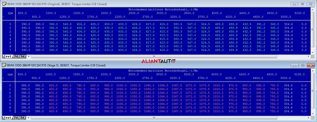
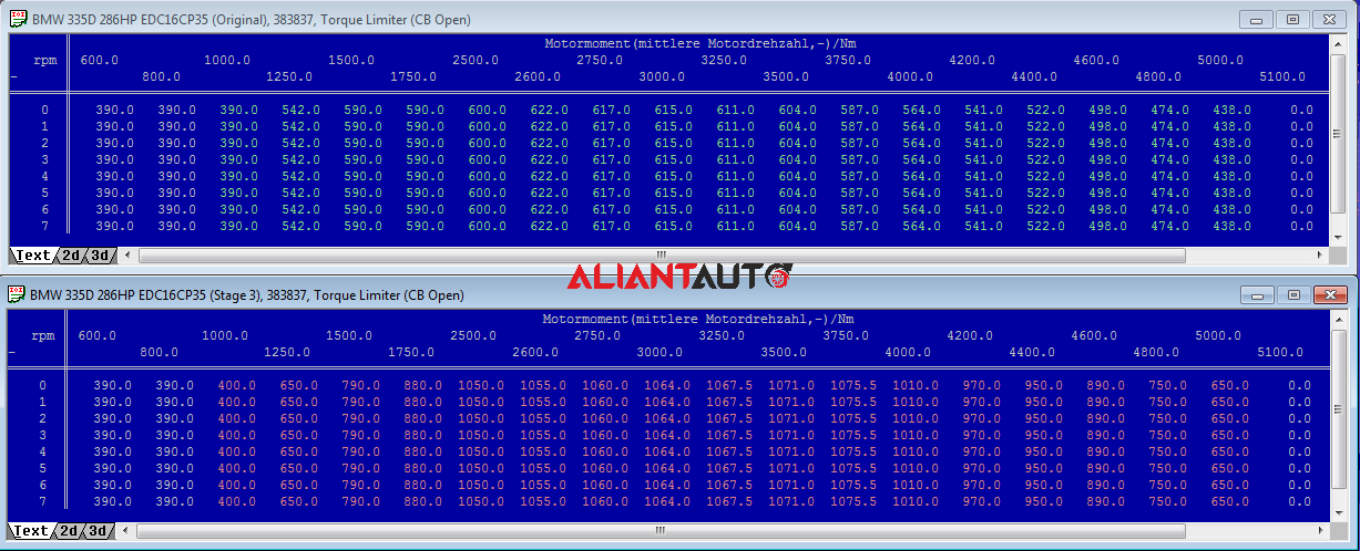
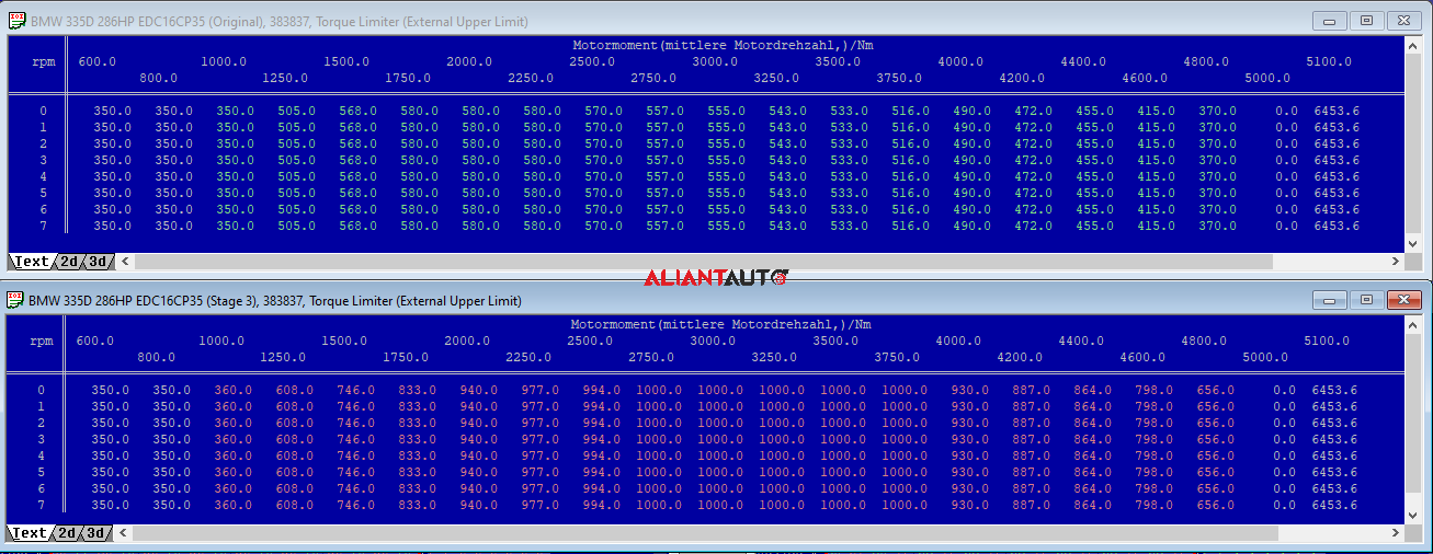
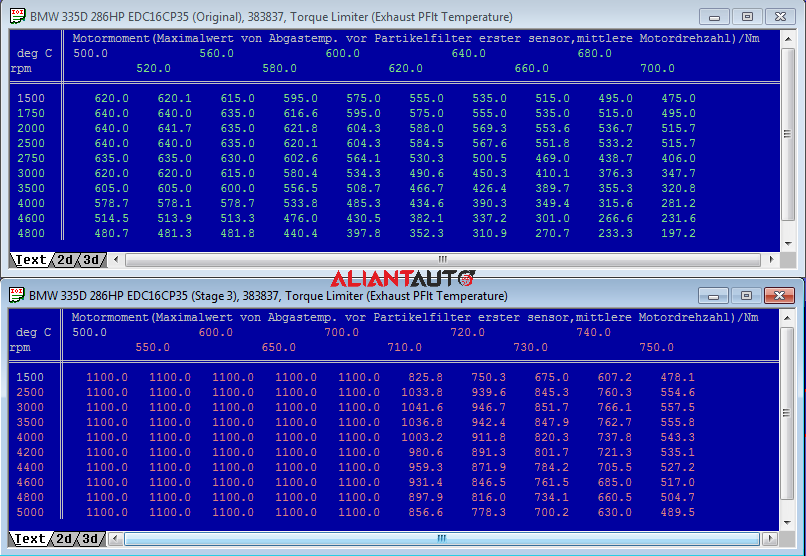
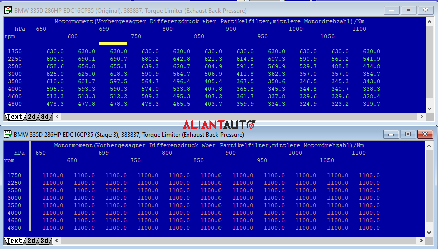
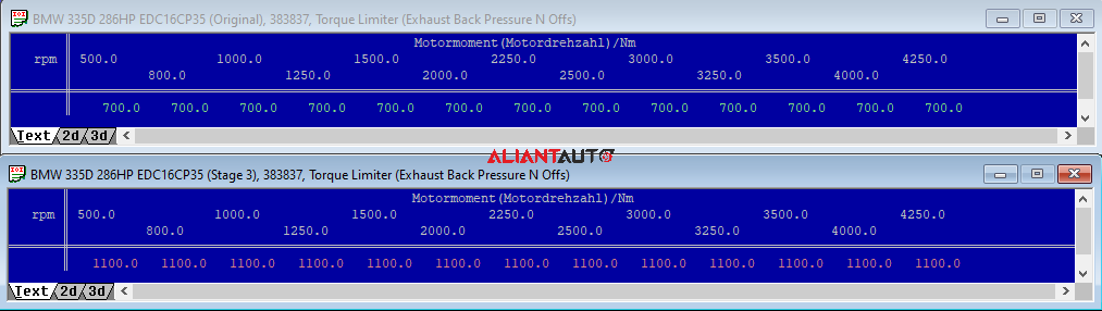
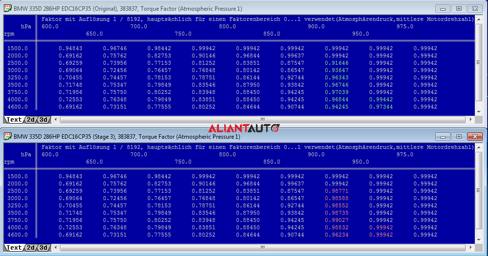
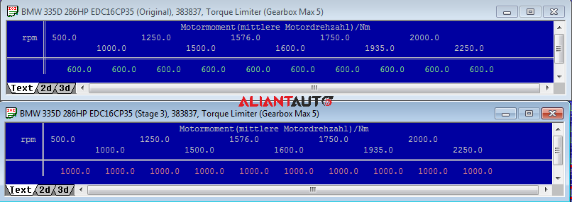
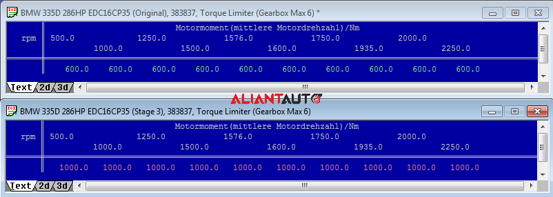
These maps are used to limit the torque based on engine RPM and other parameters to protect the engine from mechanical and thermal overloads. The result of these maps is torque measured in NM.
What should be done?
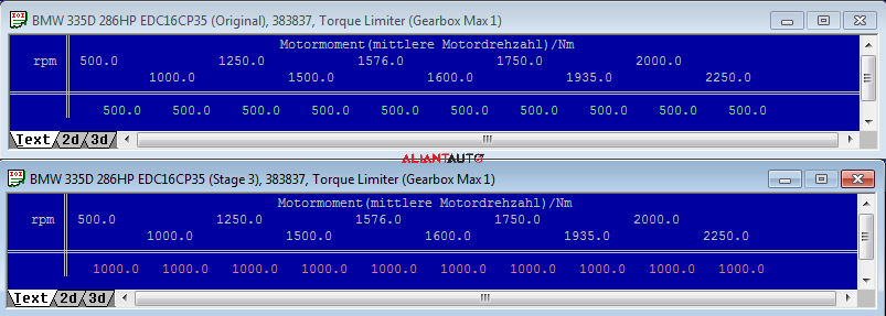
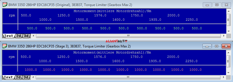
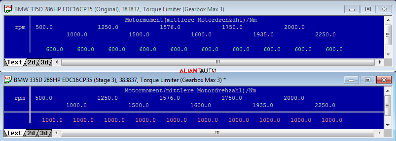
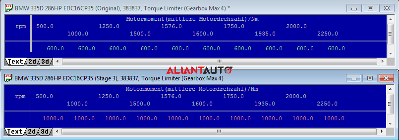
All torque maps are located and adjusted to achieve final (External) torque values of approximately 950-1000NM.
Note: It is necessary to consider the so-called internal (Internal) and external (External or Flywheel) torque maps. All torque limitation maps related to the transmission are External. The values in the maps for torque conversion to injected fuel quantity, Limp Mode maps, and all others are Internal. The main purpose of this distinction is to calculate the actual torque used by the automatic transmission control unit (TCU).
Internal Torque – Friction Torque = External Torque (Output Torque at Flywheel)
Attention!
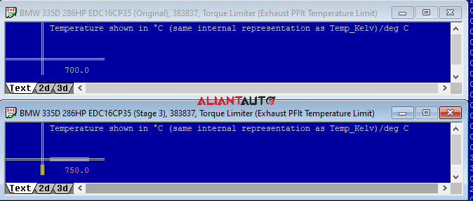
To protect the turbocharger from thermal damage, the original EGT limit is set at 700 degrees Celsius. Since this is a Stage 3 modification that significantly increases power, the temperature limit can be raised to approximately 750 degrees. Without a DPF, with sufficient boost pressure from the turbocharger, and with injectors in good condition, this temperature should not be reached, even in a Stage 3 setup!



3. Torque to IQ Maps
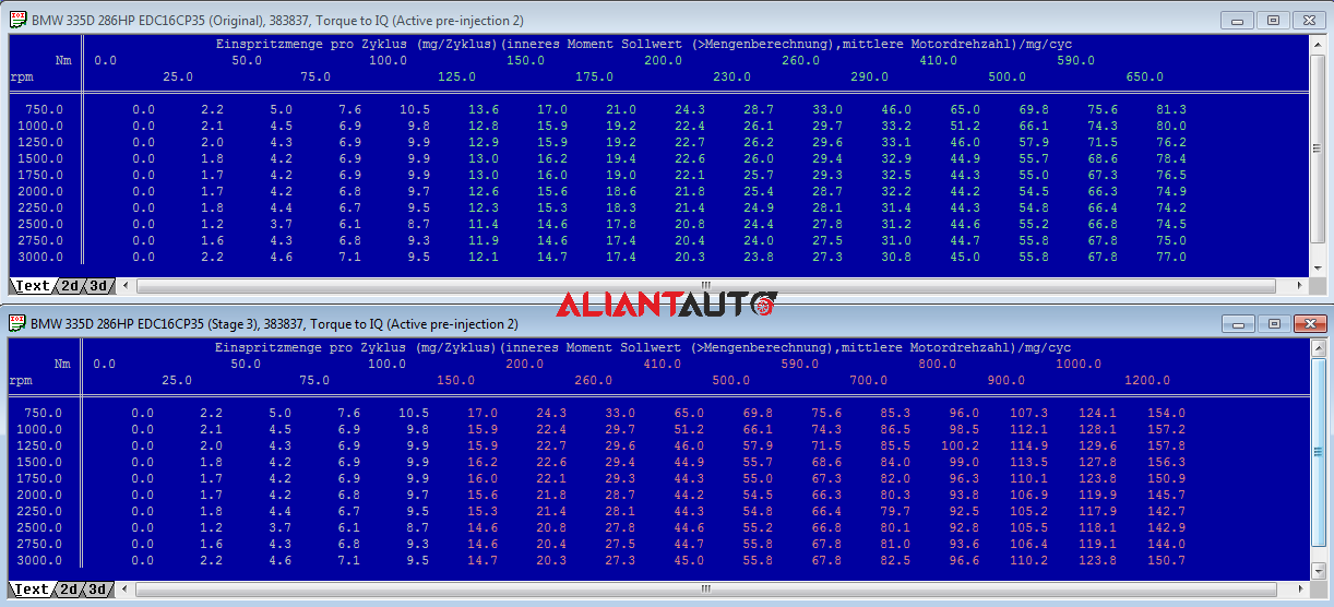
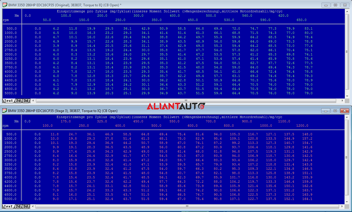
These maps are used to convert the requested torque (NM) into the amount of injected fuel (IQ) based on engine speed (RPM). As a result, the injected fuel quantity IQ is obtained in mg/hub.
What should be done?
Since the original map is calibrated up to 650NM (Internal) and the goal is a higher torque output, extrapolation is performed up to 1200NM (Internal).Note: These maps can be used to limit the injected fuel at certain RPM levels when the Lambda maps are not sufficient.
Attention!
When an automatic transmission is present, the conversion maps should always be extrapolated rather than de-calibrated! The TCU requires correct torque values from the ECU; otherwise, transmission damage may occur!

4. Lambda Maps
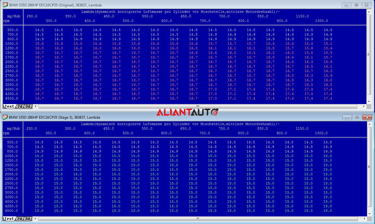
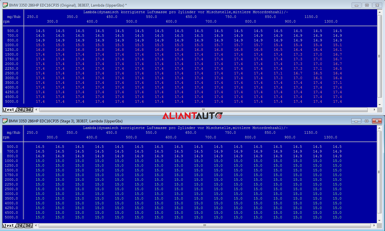
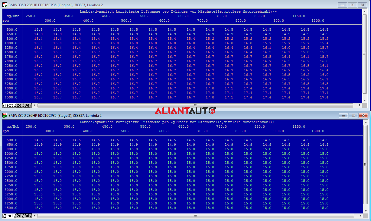
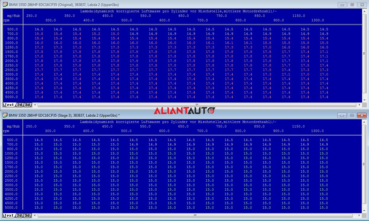
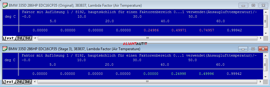
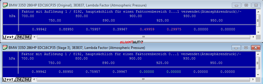
These maps are used to limit the injected fuel quantity (IQ) based on engine speed (RPM) and the measured or estimated air mass (mg/hub). The output of these maps is the Lambda value or the AFR (Air-Fuel Ratio), which determines the fuel mixture.
What should be done?
These maps, roughly speaking, determine the amount of smoke emitted from the exhaust system. This smoke results from unburned fuel. Generally, the maps are adjusted to ensure no visible smoke appears in the mirror, indicating efficient combustion.For Stage 3 tuning, lower Lambda values (richer mixture) are acceptable, as they help spool up hybrid turbochargers faster and enable higher peak power. In this case, an AFR of 15.0 is set across the entire RPM range.
Important: The optimal ratio for power, reliability, and minimal smoke levels in tuned vehicles is Lambda 1.1 – 1.2 (AFR 16 – 17.5). Deviating from this range will compromise at least one of these three aspects – an excessively rich mixture can damage the DPF (if present), turbocompresor or even the engine!
5. IQ Maps
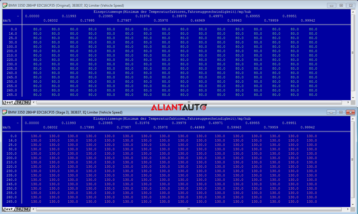
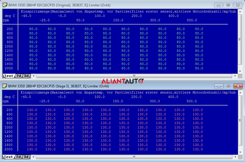
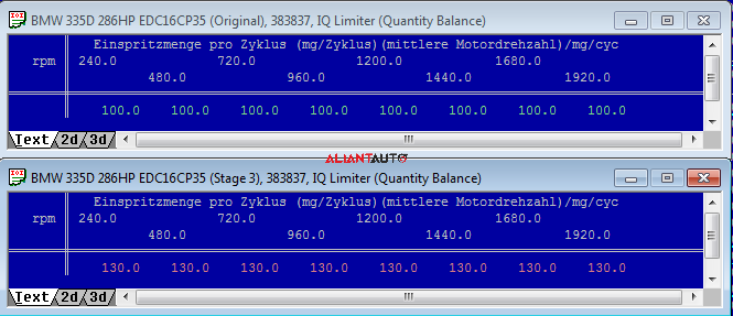
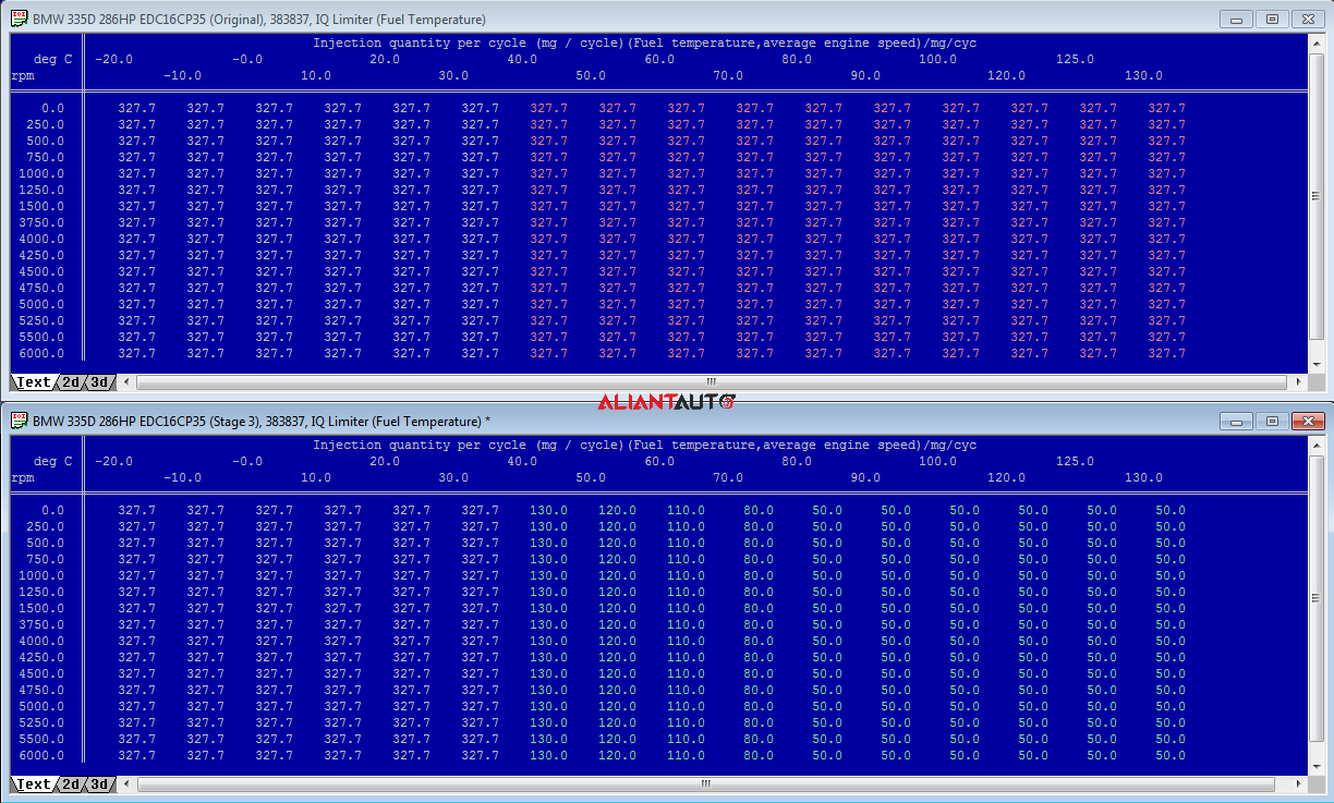
These maps are used to limit the amount of injected fuel (IQ) based on various parameters, such as coolant temperature, fuel temperature, exhaust gas temperature, vehicle speed, and others. As a result, the injected fuel quantity (IQ) is measured in mg/hub.
What should be done?
All maps are located and modified to achieve values for the maximum injected fuel quantity (IQ) of up to 130 mg/hub.
Best Practice:
It is recommended to limit torque and power until the engine reaches operating temperature or when the fuel temperature is elevated.
At Stage 3 power levels of around 480HP, the high-pressure pump (R90) operates at its maximum capacity. As the temperature rises, fuel viscosity decreases. Lower viscosity leads to a drop in system pressure, as the thinner fuel offers less resistance while passing through the internal components of the pump.

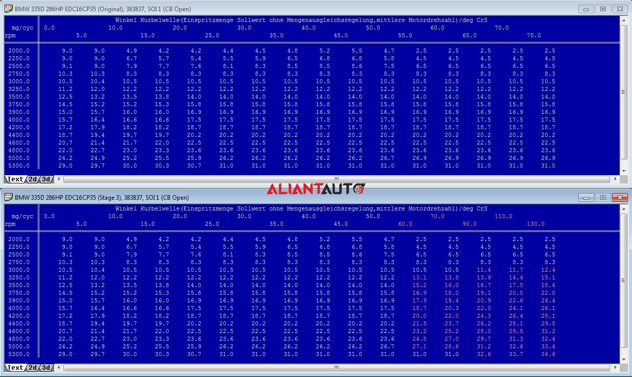
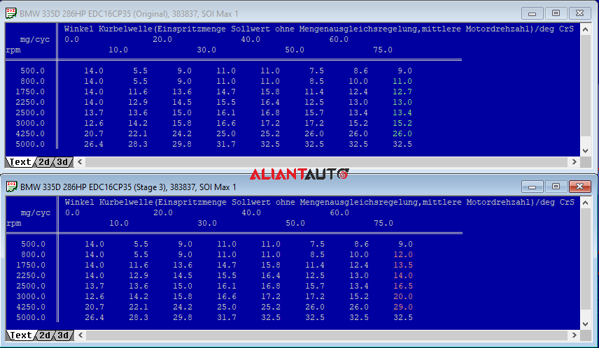
6. SOI Maps
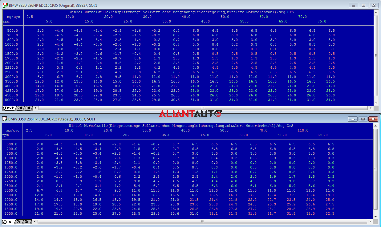
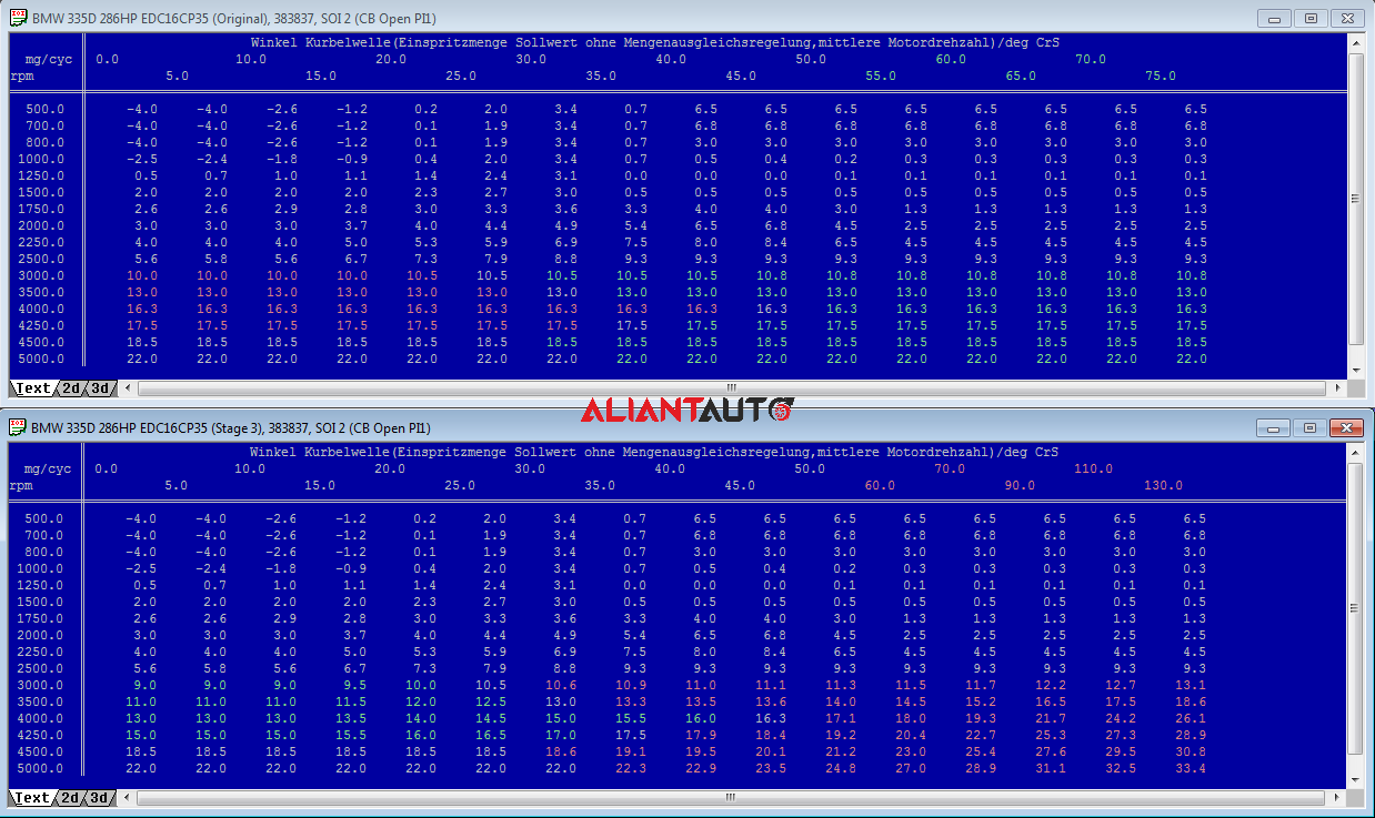
These maps are used to define the start of the main fuel injection into the cylinder. The X and Y axes represent engine speed (RPM) and the desired fuel quantity (IQ). The results of these maps are expressed in crankshaft degrees before and after the top dead center (BTDC and ATDC).
What should be done?
The start of the main fuel injection (SOI) is increased as engine speed rises. The goal is to inject up to 130 mg/hub of fuel, while the original maps are defined for lower values. Extrapolation is performed up to 130 mg/hub. Specialized software can be used to calculate the end of injection (EOI) based on injection duration and rail pressure. In principle, increasing SOI is a method for increasing power and reducing EGT. However, it should be noted that peak cylinder pressure (PCP) also rises due to the increased amount of fuel before the piston reaches the top dead center. Each engine has an optimal SOI setting, and efficiency declines if this optimal range is exceeded.
Attention! Excessively high PCP (maximum cylinder pressure) may lead to engine damage!
7. Duration Map
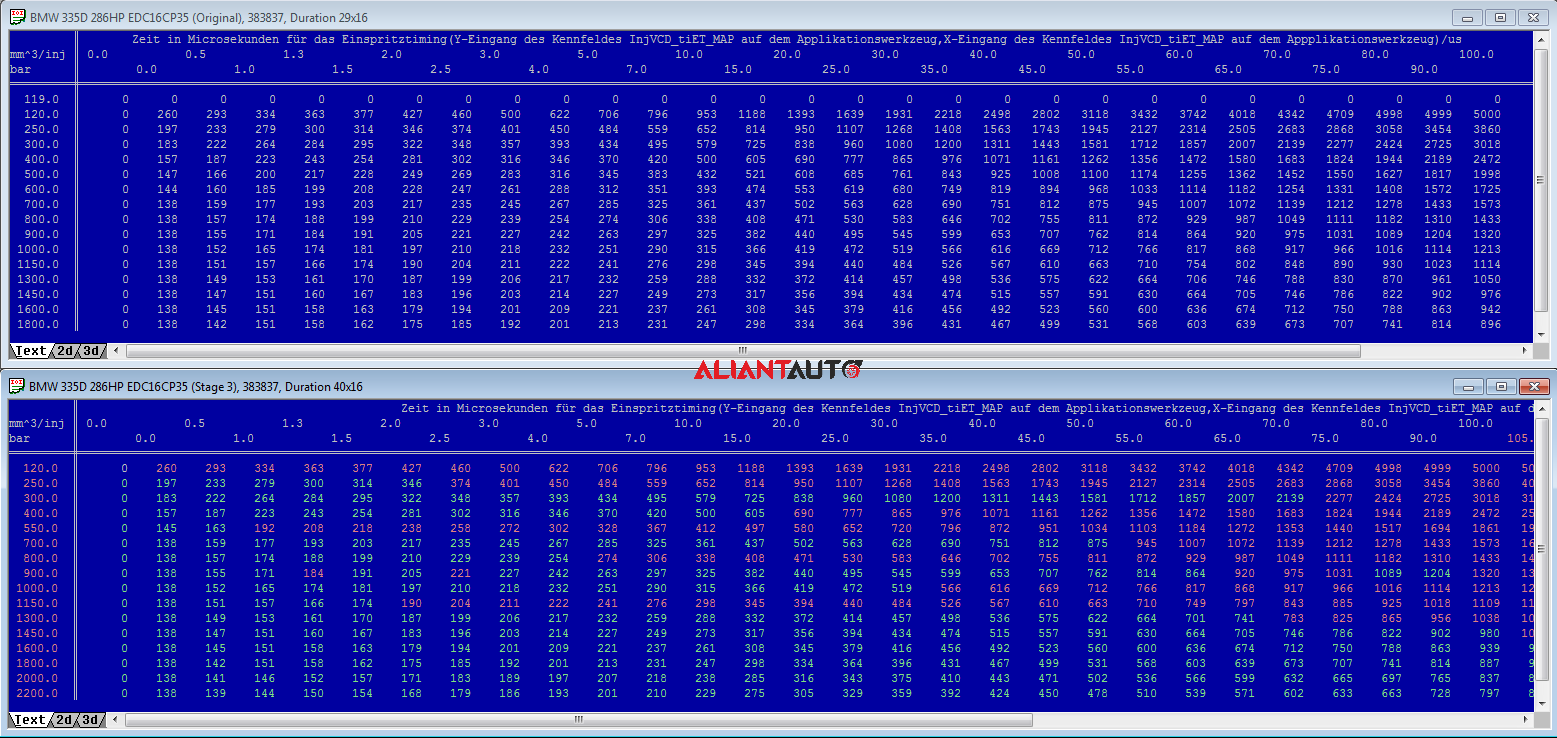
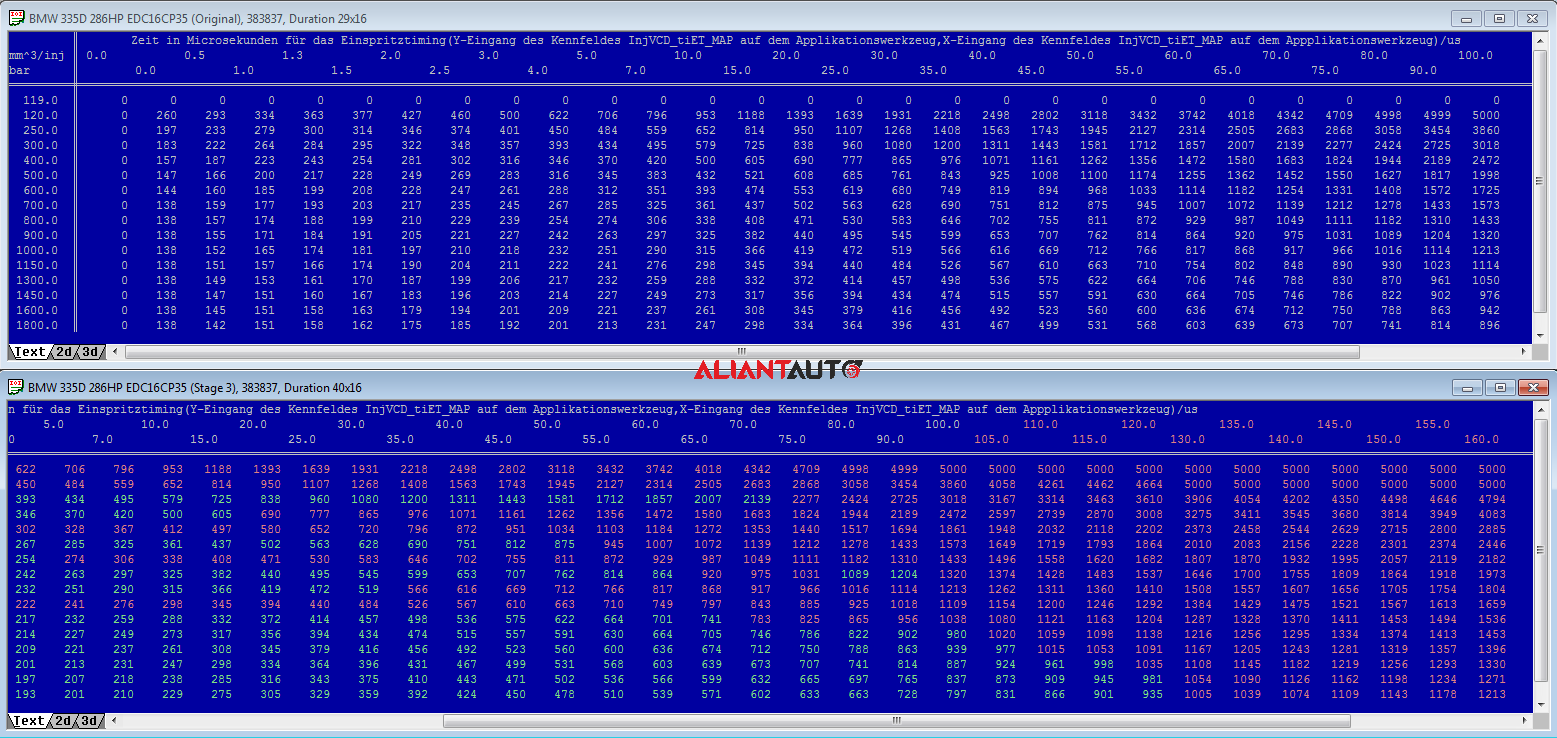
This map is used to define the fuel injection duration, or in other words, the time for which the injector remains open. The X and Y axes represent the desired fuel quantity (IQ) and the current rail pressure. The result of this map is the injection duration in microseconds (µs).
What should be done?
The duration of the main fuel injection (DOI) decreases as rail pressure increases. The goal is to inject up to 130 mg/hub of fuel, but the original map is defined only up to approximately 83.5 mg/hub (100 mm³/hub × 0.835 = 83.5 mg/hub). Extrapolation is performed up to 160 mm³/hub (133.6 mg/hub).
The rail pressure is set to 2200 bar.
Note: As a general rule, the Duration map should not be modified. Adjustments are required only if:
- The injectors are replaced with larger ones;
- More fuel needs to be injected beyond the maximum defined quantity;
- The maximum rail pressure needs to be increased.
Attention!
It should be taken into account that injection duration consists of:
- Opening time – when the injector starts to open (fuel flow changes rapidly during this time).
- Fully open phase – when the injector is completely open (fuel flow remains relatively constant).
- Closing time – when the injector is closing (similar to the opening phase).
Additionally, it should not be overlooked that the length of the first and third phases strongly depends on rail pressure. Even though a formula can be used to estimate the injected fuel quantity for a given rail pressure, the calculation is complex and not 100% precise.
8. Rail Pressure Maps
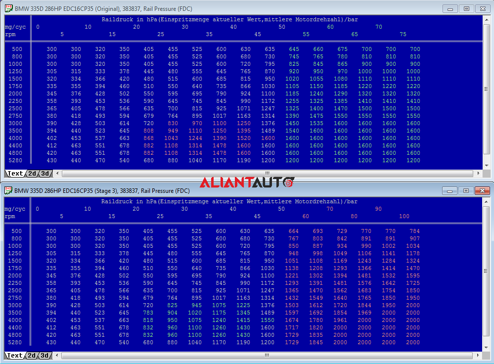
These maps are used to define the fuel pressure in the rail. The X and Y axes represent engine speed (RPM) and the desired fuel quantity (IQ). The results of these maps are the fuel pressure in the rail (hPa).
What should be done?
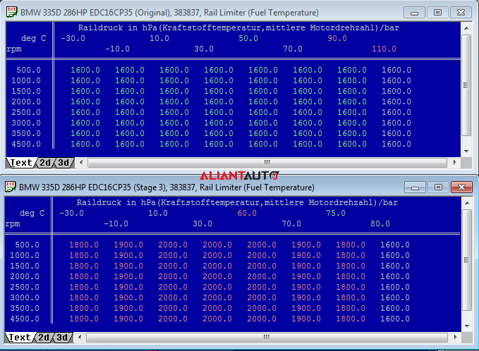
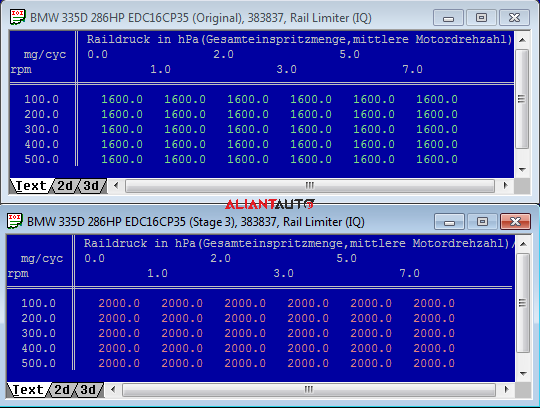
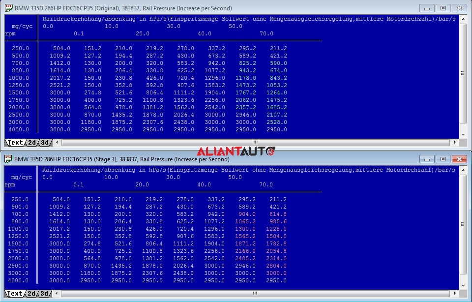
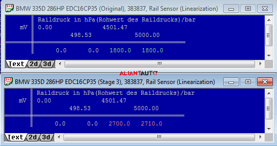
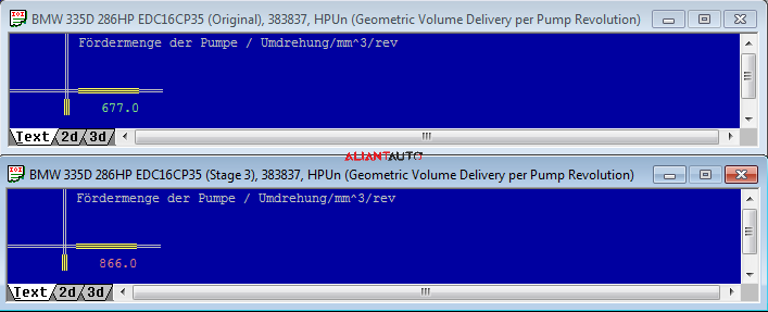
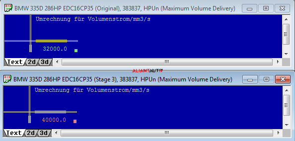
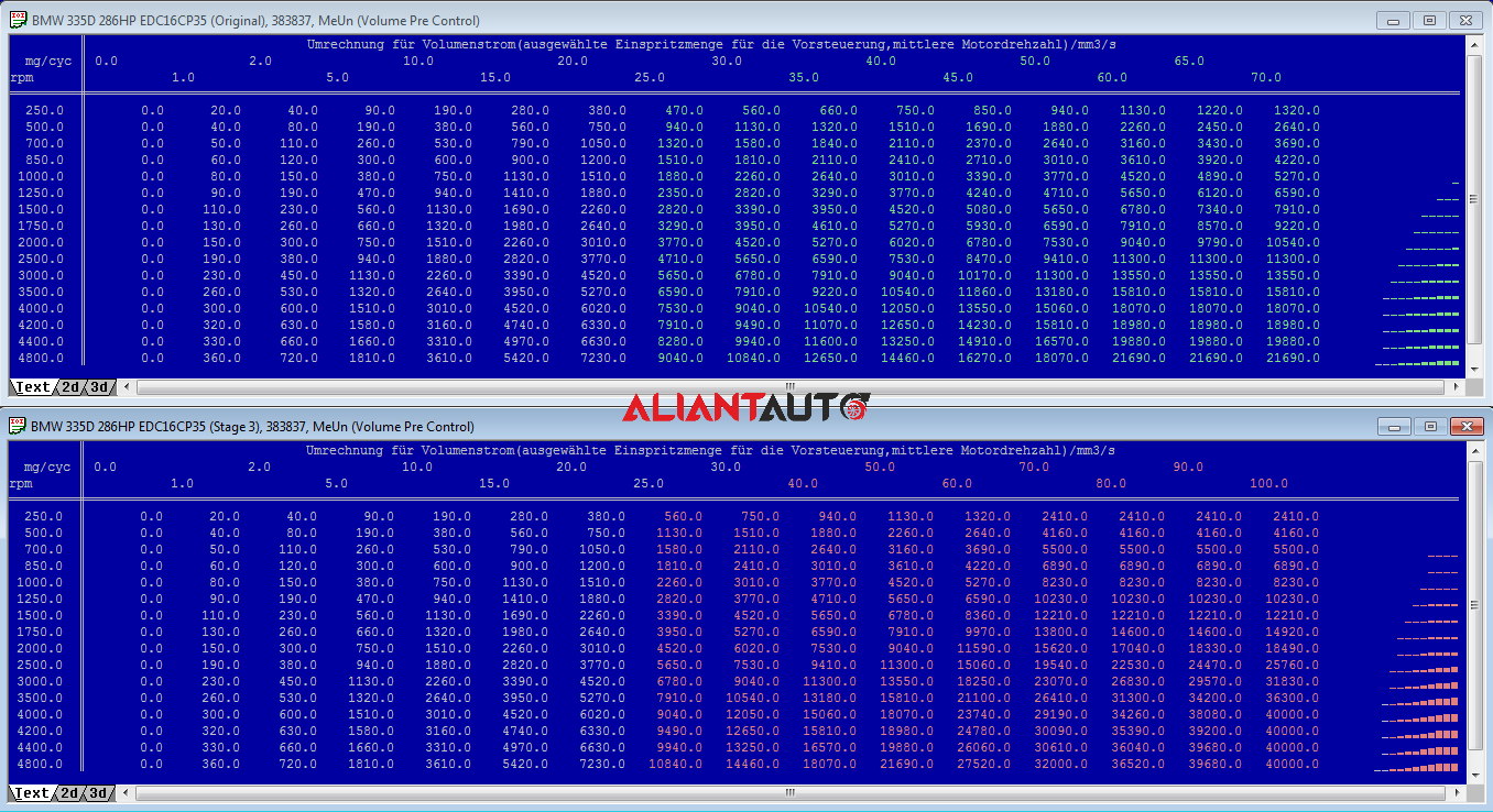
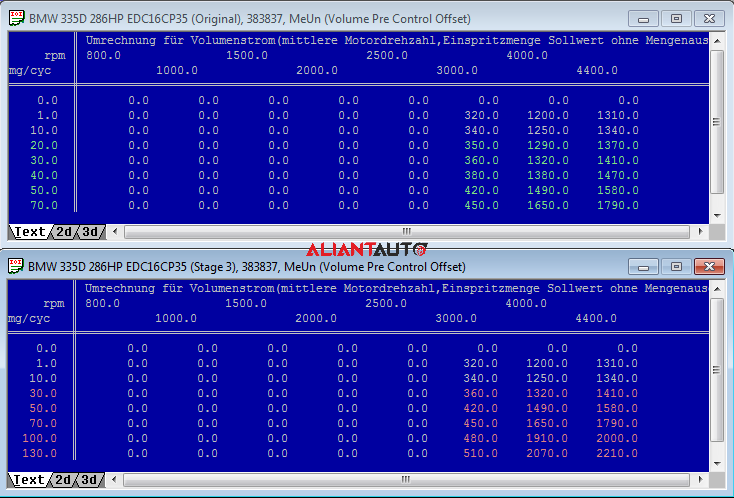
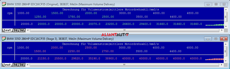
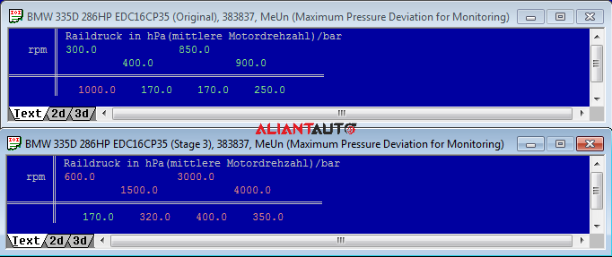
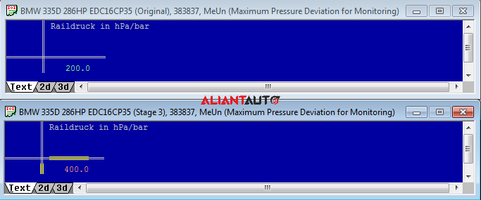
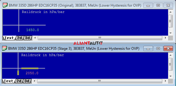
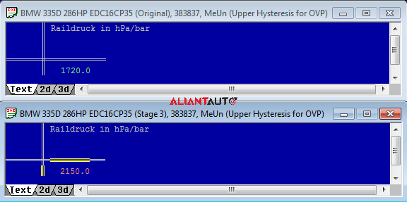
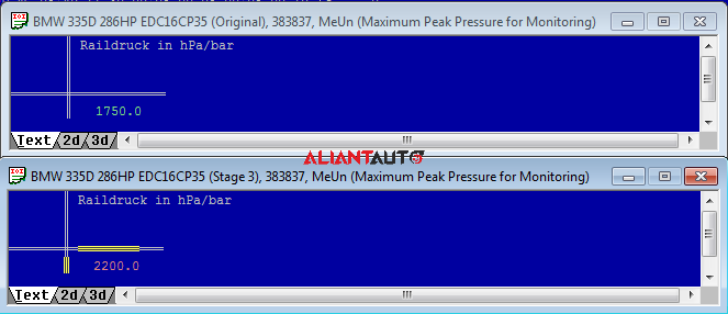
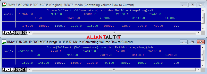
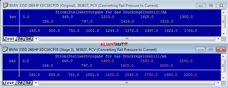
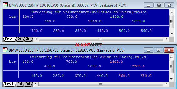
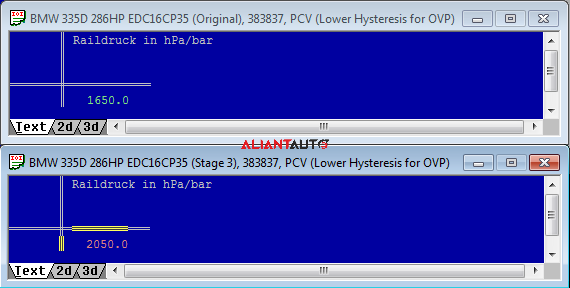
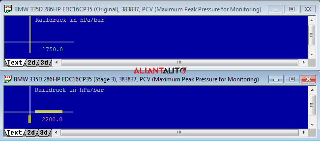
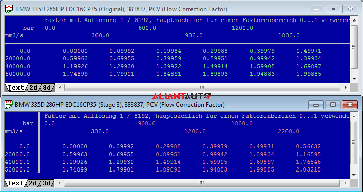
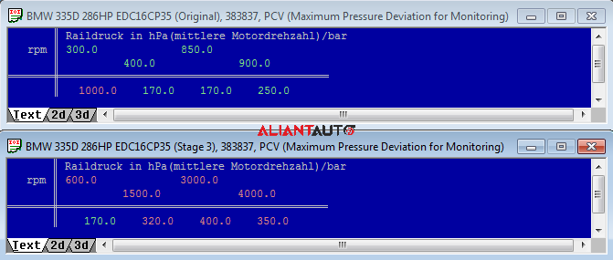
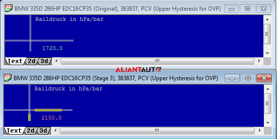
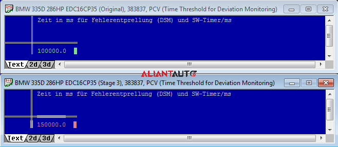
The pressure is increased to maximum values of 2000 bar, which helps ensure an optimal End of Injection (EOI). The maximum pressure is set according to the desired fuel quantity and the capacity of the high-pressure pump.
For Stage 3 and power levels around 480 HP, the original high-pressure pump and sensor must be replaced (R90, DRV30, 50D 2700bar). All of this is calibrated according to the manufacturer’s specifications, and the corresponding limiters are adjusted.
9. Boost Pressure Maps
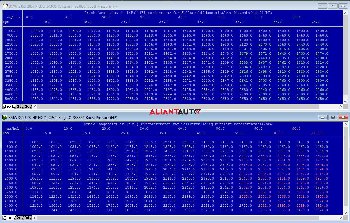
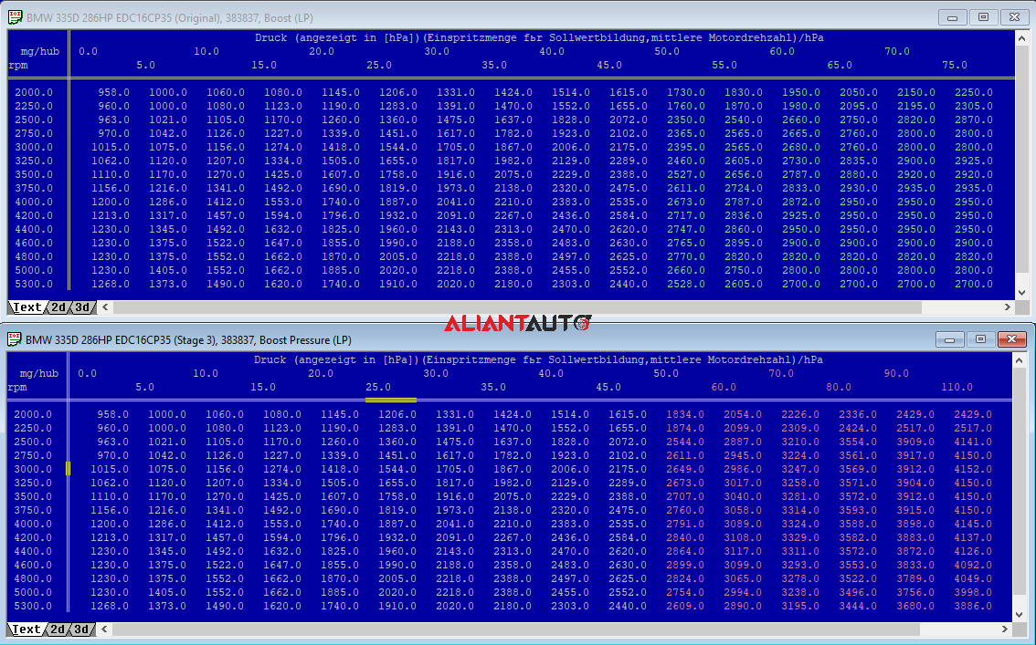
These maps are used to define the pressure of compressed air from the turbocharger. The X and Y axes represent engine speed (RPM) and the desired fuel quantity (IQ). The result of these maps is the compressed air pressure (hPa).
What should be done?
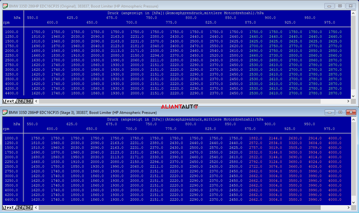
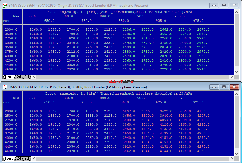
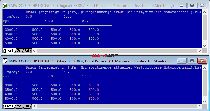
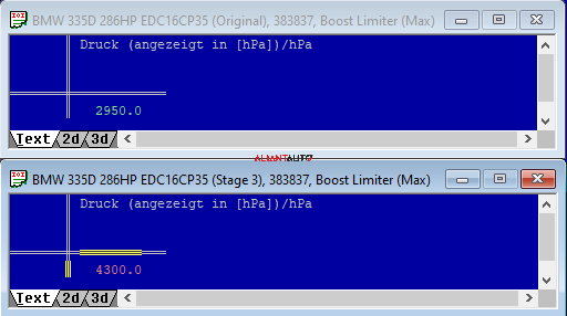
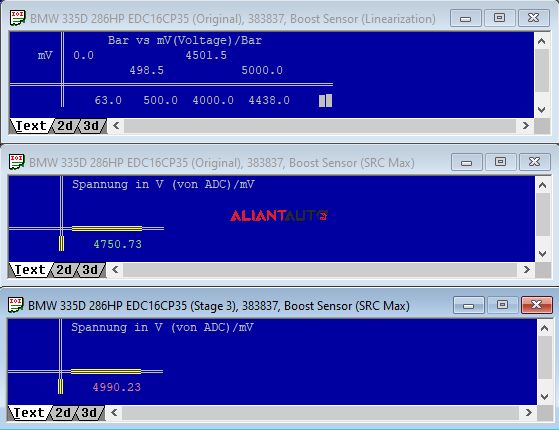
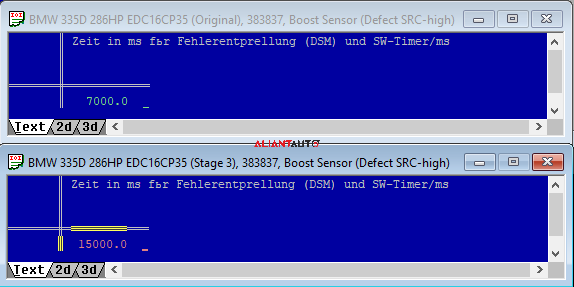
Since the goal is to inject up to 130 mg/hub at full load, the necessary amount of air must be ensured by increasing the turbocharger pressure. An absolute pressure of 4.1 bar is required, which will provide the necessary air quantity for a Lambda value of around 1.00 (AFR 15.0). The pressure is increased to a maximum value of 4150 hPa.
Interesting:
The BMW 335D is equipped with BorgWarner’s R2S turbo system, which plays a key role in enhancing engine performance and efficiency. The R2S system operates with two sequentially connected turbochargers to achieve more efficient acceleration and a broader operational range of the engine.
The airflow passes through two turbochargers with different characteristics:
High-Pressure Stage:
- The high-pressure turbocharger (the smaller one) provides high boost pressure at low RPMs, thereby improving combustion efficiency under light loads. (HP)
Low-Pressure Stage:
- The low-pressure turbocharger (the larger one) supplies a greater volume of air at higher RPMs. (LP)
- Both turbochargers are combined to ensure optimal operation throughout the entire working range.
Both turbochargers combine to provide optimal operation across the entire RPM range.
Three Control Mechanisms:
Turbine Control Valve
- The turbine control valve redirects exhaust gases to either the high-pressure turbocharger or the low-pressure turbocharger. The valve is pneumatically operated by a vacuum actuator (diaphragm unit) and can be adjusted as a percentage (Duty Cycle).
Compressor Bypass Valve
- The compressor bypass valve regulates high pressure on the intake side. It is pneumatically actuated by a vacuum actuator (diaphragm unit). The compressor bypass valve is either fully open or fully closed.
Wastegate
- When the engine reaches its nominal power, the exhaust valve opens to prevent excessive pressure. Some of the exhaust gases pass directly into the exhaust system, bypassing the low-pressure turbocharger turbine. The valve is pneumatically controlled by a vacuum actuator (diaphragm unit) and can be adjusted in percentages (Duty Cycle).
Key Operating Ranges:
Low Engine Speed Range (up to 1500 RPM)
- The turbine wheels of both the high-pressure and low-pressure turbochargers are driven by exhaust gases. The engine is primarily supplied with compressed air from the smaller turbocharger.
Medium Engine Speed Range (1500 to 3250 RPM)
- The turbine control valve gradually opens as engine speed increases.
- More exhaust gases pass through the turbine wheel of the larger low-pressure turbocharger.
High Engine Speed Range (3250 to 4500 RPM)
- The turbine control valve is fully open.
- Most exhaust gases pass through the turbine wheel of the larger turbocharger.
- The compressor bypass valve is open.
- The exhaust valve opens as RPM increases, limiting turbine speed.
The following maps are used to define boost pressure:
- PCR_pDesBas_MAP – Defines the target boost pressure for the high-pressure turbocharger up to approximately 3250 rpm. (Smaller turbocharger)
- PCR_pDesMaxAP_MAP – Sets the boost pressure limit based on atmospheric pressure.
- PCR_pBDesLP_MAP – Defines the target boost pressure for the low-pressure turbocharger after 3250 rpm. (Larger turbocharger)
- PCR_pBDesMaxAPLP_MAP – Sets the boost pressure limit based on atmospheric pressure.
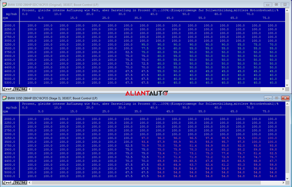
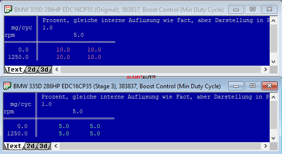
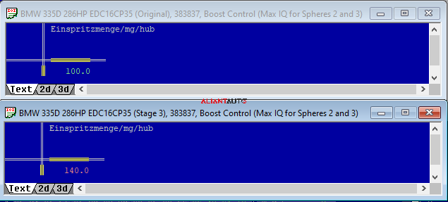
10. Boost Pressure Control Maps
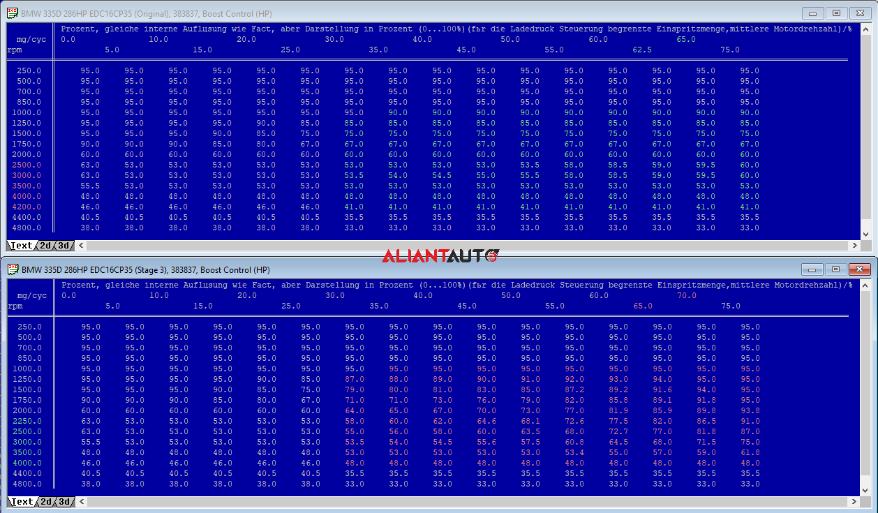
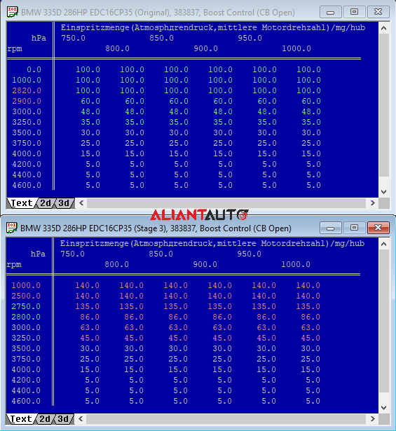
These maps define the approximate position of the actuators that control both turbochargers. The X and Y axes represent engine speed (RPM) and desired fuel quantity (IQ). The result of these maps is the approximate actuator position in percentages (%).
Why is the actuator position called approximate?
The control valve positions constantly fluctuate between fully open and fully closed. For the ECU to control these valves effectively, it must have a predefined reference for their expected position in different scenarios. The boost pressure control maps provide values close to the target, determined by fuel quantity and RPM. In some situations, the ECU dynamically adjusts these values in real-time, meaning the values in the maps may differ from those read via diagnostic tools. The more accurately the control maps are set, the better the turbocharger control will be, and the ECU’s PID correction will be minimal.
Important: If the values in the maps significantly deviate from actual conditions, the ECU cannot adequately adapt these values in real-time, and this should not be relied upon!
The following maps are used for boost pressure control:
- PCR_rCtlBas_MAP – Controls the turbine control valve (0-100%) while the compressor bypass valve remains closed.
- CpBVlv_qOpn_MAP – Sets the fuel quantity threshold for opening the compressor bypass valve. (For example, IQ > 60 mg/cyc at 2900 rpm)
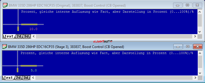
- PCR_rCBOpn_C – When the compressor bypass valve (CpBVlv) is fully open, the position of the turbine control valve is set to a constant value (10%).
- PCR_rBPBasLP_MAP – Controls the wastegate at higher engine speeds (0-100%).
- CpBVlv_qClose_MAP – Sets the fuel quantity threshold for closing the compressor bypass valve. (For example, IQ < 80 mg at 2700 rpm)
What should be done?
Fine-tuning these maps can be difficult and time-consuming, as they must work in full synchronization. Calibration is always performed using detailed logs, but only after boost pressure and fuel adjustments. This is because these fundamental parameters determine how pressure is distributed between the two turbochargers. Every car and hybrid turbocharger reacts differently to tuning. Poorly designed hybrids may make stable tuning impossible, leading to boost pressure fluctuations or overboost issues!

11. MAF Sensor Limitation
The HFM6 MAF sensor (mass airflow meter) used in the BMW 335D operates based on a frequency signal. The lower the frequency, the higher the measured air mass.
The Problem: The lowest possible frequency the sensor can detect is 232 µs, which corresponds to approximately 1250 kg/h (for BMW 35D). When this threshold is reached, the sensor maxes out and cannot measure any additional airflow.
Bosch ECU Logic
To understand the solutions, it is important to know that the Bosch ECU manages airflow calculations on three levels:
- QualityOk: The MAF sensor is operating normally, and the ECU uses the actual measured signal.
- QualityModel: The MAF sensor registers a fault (or hits its limit), but the remaining sensors are functioning correctly. In this mode, the air mass is calculated virtually by the air system model (ASMod).
- QualityDefault: In addition to a MAF fault, there is also a failure in the MAP (pressure) or IAT (temperature) sensor. Since ASMod is no longer available, a fallback value from a calibration map is used (
AFSCD_dmAirSubsVal_MAP), based on engine speed and injected fuel quantity.
Important Clarification Regarding ASMod (A common misconception): The parameter
PFlt_swtASModOn_Chas no connection whatsoever with the activation of ASMod. ASMod is permanently active and continuously generates calculated values in the background. The fact that the MAF sensor is functioning perfectly does not mean ASMod is inactive. In reality, some software modules use the measured value from the MAF sensor, while others rely on the value calculated by ASMod.PFlt_swtASModOn_Cis exactly this kind of switch. It dictates whether the DPF (Diesel Particulate Filter) calculations should use the actual measured values from the MAF sensor or the calculated values reported by the ASMod module.
Here are three ways to bypass the MAF sensor’s hardware limitation, ranked from simplest to most effective:
Method 1: Completely Disabling the MAF Sensor
This is the simplest solution, but it is a compromise. It results in poor engine performance at low and medium RPMs and increases fuel consumption.
- Implementation Step: Change the parameter
AFSCD_swtSensInstVal_Cfrom 1 to 0. (0 = OFF / 1 = ON)
Method 2: Reducing AFR Values in Lambda Maps
This method forces the ECU to inject more fuel at high airflow values. The downside is that it requires precise tuning via data logging, and every subsequent adjustment to the desired power (fuel amount) requires recalibrating the Lambda maps.
- Implementation Steps:
- Log key parameters from 2000 to 5000 RPM: air mass, injected fuel quantity, and lambda values.
- Identify the exact range where the MAF sensor reaches its maximum limit.
- Calculate and adjust the AFR values based on injected fuel and lambda readings.
Method 3: Hybrid Calculation via ASMod (The Most Elegant Solution)
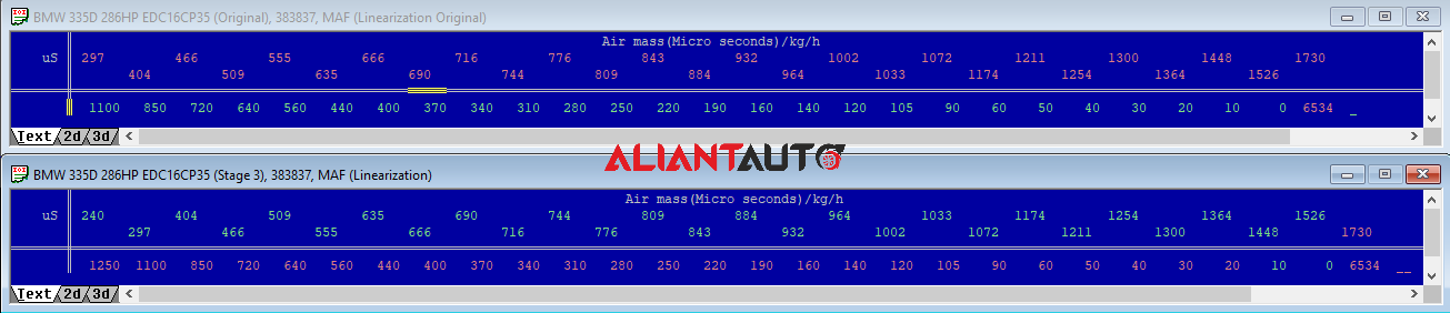
This is the best approach. It retains the precision of the MAF sensor at low and medium loads (QualityOk mode), and when the sensor maxes out at high loads, it forces the ECU to switch to MAP-based calculations (QualityModel mode via ASMod).
- Implementation Steps:
- Extend the MAF sensor linearization table: Increase its size from 27×1 to 28×1.
- Add a new value: Set a frequency of 240 µs to correspond to an airflow of 1250 kg/h.
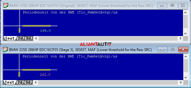
- Adjust the lower threshold for the SRC signal: Change
AFSCD_tiRawSRCLo_from 199 µs to 242 µs.Note: A 242 µs value corresponds to an air mass slightly below 1250 kg/h. This ensures that when the signal approaches 1245 kg/h, the ECU will register a dummy fault and switch to ASMod calculations. - Mask the error to allow MAF reactivation: Set
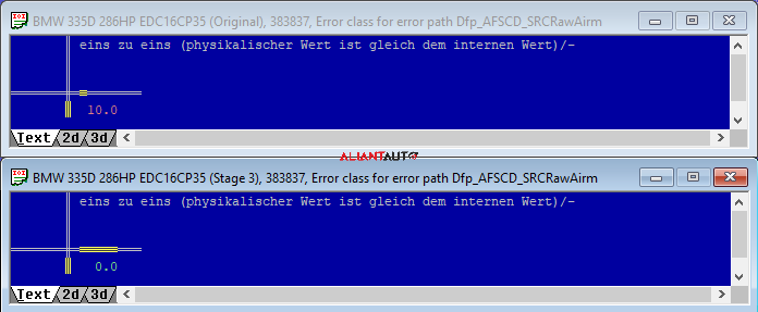
DSM_ClaDfp_AFSCD_SRCRawAirm_C= 0.Note: This „tricks“ the ECU into reusing the MAF sensor (returning to QualityOk mode) when the airflow drops below 1250 kg/h (or when the signal frequency rises above 242 µs again).
Some useful IDs:
AccPed_rFDC_CUR AccPed_trqEngHigh_MAP AccPed_trqEngLow_MAP AFSCD_DebSRCRawAirmLoDef_C AFSCD_DebSRCRawAirmLoOk_C AFSCD_swtSensInstVal_C AFSCD_tiCorrSRCHi_C AFSCD_tiCorrSRCLo_C AFSCD_tiRawSRCHi_C AFSCD_tiRawSRCLo_C AirCtl_mDesBas_MAP AirCtl_mDesBasDef_MAP AirCtl_mDesBasFDC_MAP AirCtl_qHi_CUR AirCtl_qLo_CUR BPSCD_uSRCMax_C BPSCD_uSRCMin_C CoEng_tPFltOvldLim_C CoEng_trqCorGearbxRgn_CUR CoEng_trqLim CoEng_trqLimErr1_CUR CoEng_trqLimErr2_CUR CoEng_trqLimErr3_CUR CoEng_trqLimErr4_CUR CoEng_trqLimErr_CUR CoEng_trqLimPDiff1_CUR CoEng_trqLimPDiff_MAP CoEng_trqLimPDiffNOffs_CUR CoEng_trqLimPFltOvld_MAP CpBVlv_qClose_MAP CpBVlv_qOpn_MAP DSM_CDCDfp_AFSCD_SRCRawAirm_C DSM_CDKDfp_AFSCD_SRCRawAirm_C DSM_CDKDfp_PFltChar_C DSM_CDKDfp_PFltPresDynPlaus_C DSM_CDKDfp_PFltPresPlaus_C DSM_CDKDfp_SWChk_CycSigChkDat_C DSM_CDKDfp_SWChk_CycSigChkPrg_C DSM_ClaDfp_AFSCD_SRCRawAirm_C DSM_RdyCDForceMsk_C EGT_stRgnLckMsk_C EGT_swtEGTActv_C Eng_trqSpd_CUR EngPrt_facAPSPrv_MAP EngPrt_facAPSPrv_MAP EngPrt_facOvhtPrv_MAP EngPrt_facOvhtPrv_MAP EngPrt_facOvhtPrvCT_CUR EngPrt_facOvhtPrvCT_CUR EngPrt_facOvhtPrvFT_CUR EngPrt_facOvhtPrvOT_CUR EngPrt_nOvrSpd_C EngPrt_qOvht_MAP EngPrt_qOvhtPrvNRng_MAP EngPrt_qOvhtPrvVRng_MAP EngPrt_swtSensOvht_C EngPrt_tiDebOvhtOk_C EngPrt_tOvhtLim_C EngPrt_trqCBLim_CUR EngPrt_trqLim_CUR EngPrt_trqLimDA_CUR EngPrt_trqNLim_CUR EngPrt_trqNLimSpr_CUR FanCtl_dcycAftRun_C FanCtl_nSetGbxOil_MAP FanCtl_nSetGbxOil_MAP FanCtl_nSetPnt_MAP FlMng_dqSlpNeg_C FlMng_dqSlpPos_C FlMng_facLmbdAPSCor_CUR FlMng_facLmbdATSCor_CUR FlMng_FullLdRglIKi_CUR FlMng_FullLdRglPKp_CUR FlMng_FullLdRglPKp_CUR FlMng_FullLdRglPKp_CUR FlMng_FullLdRglPKp_CUR FlMng_qFullLdRglMax_C FlMng_qFullLdRglMin_C FlMng_rLmbdRecDvtMax_C FlMng_rLmbdRecDvtMin_C FlMng_rLmbdSmk2_MAP FlMng_rLmbdSmk2UpperGbx_MAP FlMng_rLmbdSmk_MAP FlMng_rLmbdSmkDef_MAP FlMng_rLmbdSmkUpperGbx_MAP FlMng_stEGTRglOff_C FlMng_tiFullLdRglDel_CUR FlMng_trqEpsLim_C FlSys_rhoFl_CUR FMTC_swtCorr_C FMTC_trq2qBas_MAP FMTC_trq2qBasCBOpn_MAP FMTC_trq2qBasPiI2_MAP FrmMng_swtTORQUE_GEARBX_C Gearbx_trqInMax_CUR Gearbx_trqMaxErr2_CUR Gearbx_trqMaxErr_CUR Gearbx_trqMaxGear1_CUR Gearbx_trqMaxGear2_CUR Gearbx_trqMaxGear3_CUR Gearbx_trqMaxGear4_CUR Gearbx_trqMaxGear5_CUR Gearbx_trqMaxGear6_CUR Gearbx_trqMaxGearR_CUR HPUn_dvolMeUnMax_C HPUn_qBalLim_CUR HPUn_qFlTempLim_MAP HPUn_volPmp_C IndSys_rVSAMAX_C InjCrv_phiMI1Bas1_MAP InjCrv_phiMI1Bas1CB_MAP InjCrv_phiMI1Bas2_MAP InjCrv_phiMI1Bas2CB_MAP InjCrv_phiMI1Bas3_MAP InjCrv_phiMI1Max2_MAP InjCrv_phiMI1Max_MAP InjCtl_qLimErr_MAP InjVCD_tiET_MAP InjVCD_tiET_MAP InjVlv_facFTSWvCor_MAP InjVlv_facVoltCorUp_MAP MeUn_iCnvFlowRate_CUR OxiCCD_tLinPre_CUR OxiCCD_uSRCMaxTPre_C OxiCCD_uSRCMinTPre_C PCR_DebSRCHighDef_C PCR_DebSRCHighOk_C PCR_pBDesLP_MAP PCR_pBDesMaxAPLP_MAP PCR_pBGDevMax_MAP PCR_pDesBas_MAP PCR_pDesMax_C PCR_pDesMaxAP_MAP PCR_pFltValLim_C PCR_pLPDvtMax_MAP PCR_qWrkSph3_C PCR_rBPBasLP_MAP PCR_rBPCtlBasAirCtlOff_MAP PCR_rBPRglBasLP_MAP PCR_rCBOpn_C PCR_rCtlBas_MAP PCR_rGvnrMax_MAP PCR_rGvnrMin_MAP PCR_rSurgeCtlVal_MAP PCV_dvolLeak_CUR PCV_facAdaptFlow_MAP PCV_iCnvPress_CUR PCV_iSetMax_C PCVCD_dcycMax_C PFlt_DebCharMaxDef_C PFlt_DebCharMaxOk_C PFlt_DebCharMinDef_C PFlt_numEngPOpDel_CA PFlt_numEngPOpIntr_CA PFlt_pDiffHsLnNeg_C PFlt_pDiffHsLnNeg_C PFlt_pDiffMax_C PFlt_pDiffTolcMax_C PFlt_pPreTolcMax_C PFlt_tEGMax_C PFltCD_tLinPre_CUR Prp_rEng_MAP PrpCtl_swtSpdLimType_C PrpCtl_swtSpdLimVal_C PSPCD_dvolBase_CUR PSPCD_dvolMax_C Rail_DebMeUn0MaxDef_C Rail_DebMeUn0MaxOk_C Rail_DebMeUn1MaxDef_C Rail_DebMeUn1MaxOk_C Rail_DebMeUn3MaxDef_C Rail_DebMeUn3MaxOk_C Rail_dpSetPointInc_MAP Rail_dvolMeUnCtlLoLim_C Rail_dvolMeUnCtlUpLim_CUR Rail_dvolMeUnSetMin_C Rail_dvolPreCtlBas_MAP Rail_dvolPreCtlOfs_MAP Rail_pMeUnDvtMax_C Rail_pMeUnDvtMax_CUR Rail_pMeUnPeakMax_C Rail_pMeUnPeakMin_CUR Rail_pNIPCVMax_MAP Rail_pOvrMeUnThresHigh_C Rail_pOvrMeUnThresLow_C Rail_pOvrPCVThresHigh_C Rail_pOvrPCVThresLow_C Rail_pPCVCtlUpLim_C Rail_pPCVCtlUpLim_C Rail_pPCVDvtMax_CUR Rail_pPCVPeakMax_C Rail_pPCVSetMax_CUR Rail_pSetPointBase_MAP Rail_pSetPointBaseFDC_MAP Rail_pSetPointLimNFlTemp_MAP Rail_pSetPointMax_MAP Rail_qMeUnLoIdle_C Rail_tiThresMonEna_C RailCD_pLin_CUR RailCD_uOfsAftRunMax_C RailCD_uOfsAftRunMin_C RailCD_uSRCMax_C RailCD_uSRCMin_C Sig_mAirCylDIAOffset_C Sig_mAirCylDIAScale_C Sig_pRailDIAOffset_C Sig_pRailDIAScale_C Sig_qCANScale_C Sig_qDIAOffset_C Sig_qDIAScale_C Sig_qDSMOffset_C Sig_qInjMassCycCANScale_C Sig_qInjMassCycDIAOffset_C Sig_qInjMassCycDIAScale_C Sig_qInjMassDIAOffset_C Sig_qInjMassDIAScale_C Sig_volRailDIAOffset_C Sig_volRailDIAScale_C TVACD_rOutMax_C VSSCD_vMax_C