ECU Remap Guide – MED9.1 Seat Leon Cupra 2.0TFSI 20V 240HP – Stage 2
06.03.2025This short guide provides step-by-step instructions for a Stage 2 remap of the SEAT LEON CUPRA 2.0TFSI 240HP with the MED9.1 ECU. It is designed for enthusiasts looking to unlock more engine potential and perform the remap themselves. I have simplified the process to make it as clear as possible.
If you have any questions, feel free to message me directly on Facebook Messenger: https://www.facebook.com/aliantauto.
Before You Start
If you are unfamiliar with the key components of a gasoline engine—such as the fuel system, cooling system, exhaust system, turbocharger, or sensors like MAF and MAP; if you don’t understand how the air-fuel mixture and ignition timing affect power and combustion; if you’ve never heard of O₂ Lambda Control, the difference between Narrowband and Wideband O₂, or STFT and LTFT, and cannot dedicate at least 2-3 hours a day for 1-3 months to learning the fundamentals and testing your attempts, this guide may not be suitable for you.
For complete beginners, it might be better to read the articles in the General section before going through this guide.
What You Need for a Successful Stage 2 Remap
- Car: SEAT LEON CUPRA 2.0TFSI 240HP with an MED9.1
- Diagnostic Tool: Used to log real-time data after each modification.
- Examples: VCDS, VAS, VehiCAL.
- ECU Programming Tool: Required to read the original file and write modified files.
- Examples: MPPS, Galletto v54, Alientech Kess V2.
- Battery Stabilizer: It is recommended to maintain stable voltage during the reading and writing files.
- Example: GYSFLASH 100.12 HF.
- WinOLS Software: A specialized tool for modifying ECU memory content, making it easier to find and edit maps.
Key Guidelines
Before modifying any factory settings, you must evaluate the vehicle’s current condition by logging essential parameters such as: Mass airflow, Turbo pressure, Rail pressure, Fuel mixture, etc. For gasoline engines, logging should be done in 3rd or 4th gear, from 2000 to 6500 RPM, at 100% throttle. Use specialized software and interfaces compatible with your car brand. If you detect deviations from factory parameters, resolve them before making any modifications to the ECU file!
When you are a beginner and lack experience, I advise you to change parameters in small increments and monitor how they affect the vehicle through logging. If at any point you do not know or are unsure of the consequences of certain changes, it is best to do nothing and continue searching for information!
By following these guidelines, you can successfully complete a Stage 2 remap and enhance your vehicle’s performance while minimizing risks.
Example Stage 2. Includes the following modifications to the vehicle:
- Intake Upgrade – Ramair
- Intercooler Upgrade
- Fuel Pump (HPFP) Upgrade – Vis motorsport
- Fuel Rail Valve (FPRV) Upgrade – RS4 version
- Crankcase Ventilation and PCV Upgrade
- Custom Downpipe
Here, I will describe the main maps required for this specific Stage 2, which includes increasing the power to around 350HP and 450NM. I provide brief explanations for each type of map, while all other maps are uploaded to the respective album on my Facebook page.
If you have any questions or would like me to send you a package with all maps (Mappack.kp), please send a private message to my Facebook Messenger: https://www.facebook.com/aliantauto.
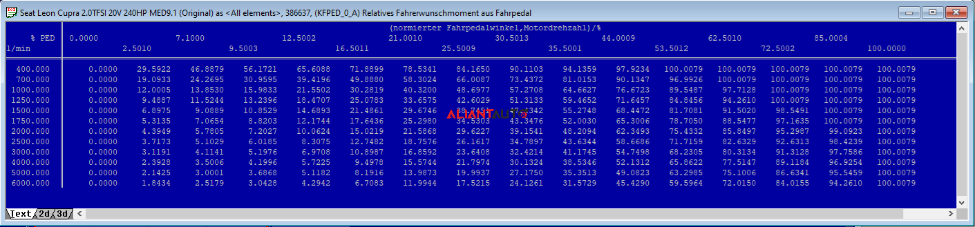
1. Driver Wish Maps – KFPED
These maps are responsible for the request of torque (mrfa_w) in percentage (from 0% to 100%) based on engine speed (nmot_w) and throttle pedal position (wped_w).
What should be done?
These maps are left unchanged. They may be modified when a difference in throttle pedal response is desired.
Note: Several maps with this function exist. Each of them is responsible for requesting torque in percentage, depending on different operating modes. KFPED, (KFPED_0_A, KFPED_1_A), KFPEDL (KFPEDL_0_A, KFPEDL_1_A, KFPEDL_2_A), KFPEDR
2. Torque To Load Map – KFMIRL
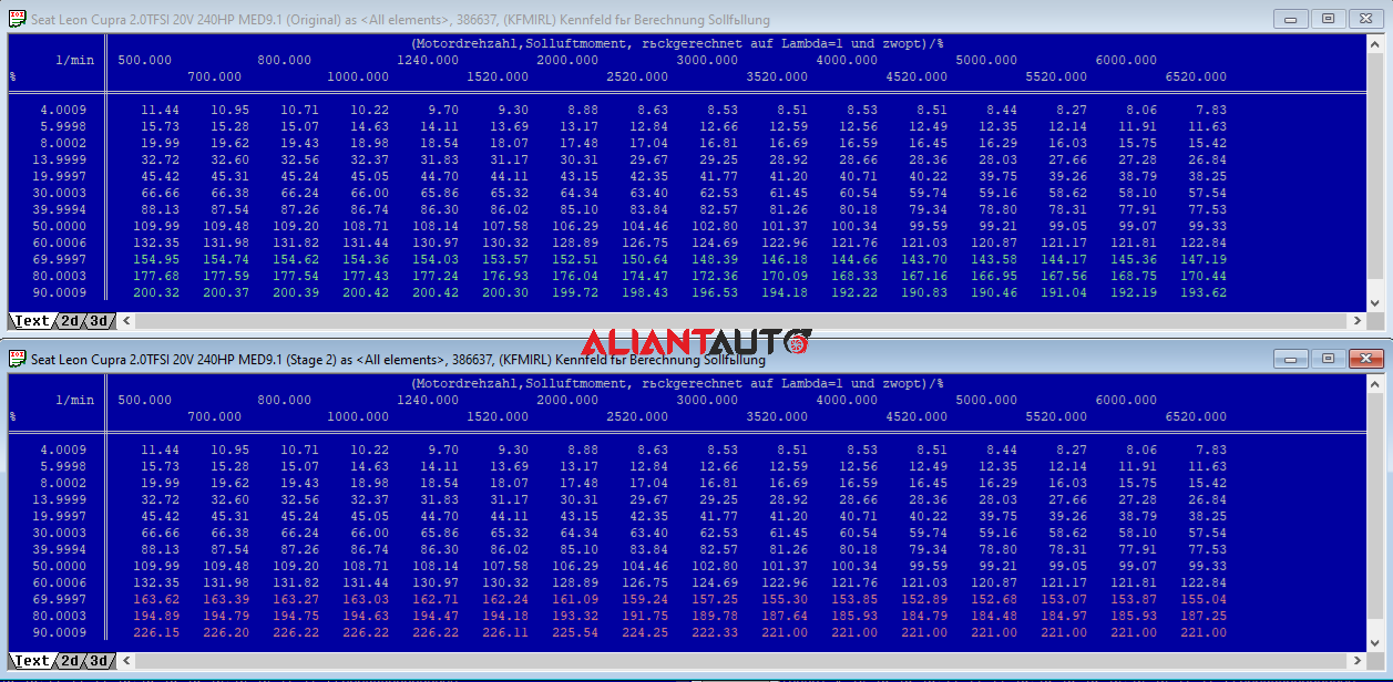
This map converts the requested torque from the throttle pedal (%) into „target load“ or „cylinder filling request percentage“ (Load (%)) according to engine speed (nmot_w). The result is a request for cylinder filling percentage (rlsol_w).
What should be done?
Since the goal is to increase power under full load (at 90-100% requested torque from the throttle pedal), the request for cylinder filling percentage (Load) in this range must be increased. It must be ensured that when a full load request (100%) is made, a sufficient cylinder filling percentage (Load) is requested, which is greater than that set in LDRXN (LDRLMX) (see below).
Note: In the early TFSI engines like AXX, there are two KFMIRL maps. In later-produced engines like BWA, there is only one KFMIRL map, which is used across all different operating modes (homogeneous, homogeneous-lean, homogeneous split, stratified injection, catalytic converter heating).
3. Load To Torque Map – KFMIOP
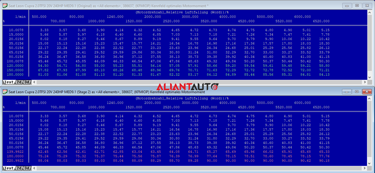
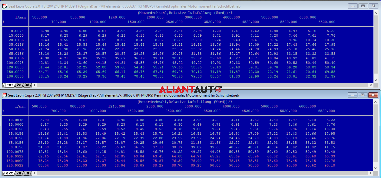
This map converts the actual (rl_w) and/or the maximum allowable cylinder filling percentage (rlmax_w) into actual (mibas_w) and/or maximum (mimax_w) torque, according to engine speed (nmot_w). The result is the actual and/or maximum torque in percentage (0% – 100%). KFMIOP is the inverse of KFMIRL. It is mainly used for torque monitoring.
What should be done?
The map is adjusted so that it is the inverse of the Torque To Load (KFMIRL) map. Care is taken to set precise values in the map (and along the Load axis); otherwise, intervention in actual torque (Torque Interventions) may occur.Note: This map essentially performs the opposite function of the Torque To Load map. The resulting actual torque is used for other ECU functions that require actual torque values (Torque Intervention, ESP, DSG, etc.). The presence of a Load To Torque map saves additional computational work for the processor.
4. Torque Monitoring (Level 1) Мaps
4.1 – KLMIMAX
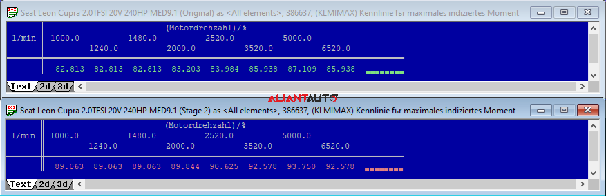
This map defines the primary characteristic for monitoring the maximum torque (Level 1).
What should be done?
The map is modified so that the values are greater than or equal to the maximum values in KFMIOP. To prevent interference in torque from Level 1, the following conditions must be met: (mibas < miszul) && (mimax < miszul).Note: The KLMIMAX map is part of a complex torque monitoring algorithm (MDZUL). Depending on the specific ECU models, the algorithm includes maps such as KLLLRZU, KFPZU, KLMZUMN, KFMOF, etc. In cases of active interventions increasing the torque or active cruise control adjustments, the maximum torque characteristic is determined by a single value – MDIMX (~100%).
Important: Maps ending in _UM and _UC should never be modified. They are used by the Level 2 protection, which has no relevance to the calibration of the main maps. Instead, these maps verify whether the mathematical expressions of the ECU functions operate correctly.
5. Main Load Limiter Maps – LDRXN, LDRXNZK
These maps limit the request for cylinder filling percentage (rlsol_w) based on engine speed (nmot_w). These are the primary maps used to limit torque (NM) and power (HP) for this type of ECU. The result of these maps is the maximum desired cylinder filling (rlmx_w) in percentage.
What should be done?
The LDRXN map is broadly responsible for the maximum allowed real torque (NM) and power (HP) across all RPMs. Since the goal is to increase torque and power under full load, the limit on cylinder filling percentage (Load) must be increased according to the set objectives. For this specific Stage 2 with around 350HP, a maximum cylinder filling of approximately 220% is required.LDRXN is a base map. The final cylinder filling percentage (rlmax_w) may be altered if, for example, measured turbocharger pressure exceeds norms, or if various factors apply: intake air temperature, coolant temperature, prolonged knock occurrences. All these factors may increase or decrease the cylinder filling percentage request set by the LDRXN map. The final result (rlmax_w) limits the outcome of KFMIRL (rlsol_w).
Note: The MED9 does not have a map that sets the desired turbocharger pressure. The ECU calculates the necessary pressure based on the cylinder filling percentage request (Load). There is an approximate formula used to estimate the expected pressure based on the LDRXN values:
Requested Boost = (LDRXN * 10) + 300mbar
If LDRXN = 220%, then:
Requested Boost = (220 * 10) + 300 = 2200 + 300 = 2500 mbar (absolute pressure).
It should be noted that this is a rough conversion from cylinder filling percentage to turbocharger pressure. The actual value may differ by up to 30% or more, depending on several factors such as air density, temperature, altitude, and more.
There are several maps with this function. Each of them is responsible for limiting the cylinder filling (Load) according to different operating conditions.
- LDRXN is used under normal conditions without detonation (LDRXN_0_A, LDRXN_1_A, LDRXN_2_A).
- LDRXNZK is applied in cases of prolonged detonation (LDRXNZK_0_A, LDRXNZK_1_A, LDRXNZK_2_A).
Real-world scenario: Driving on the highway at 140 km/h in 5th gear at 2500 RPM, the throttle pedal is pressed to 45% to maintain speed. Looking at the relative torque request map (KFPED), the value at X = 45% and Y = 2500 RPM is approximately Z = ~60%. Then, checking the cylinder filling percentage request map (KFMIRL), the value at X = 2500 RPM and Y = 60% is around Z = 127%. The decision on whether 127% cylinder filling can be requested is determined by the LDRXN limitation map. Checking this map, the value at 2500 RPM is 143%. This means that the requested filling from KFMIRL is below the safe limit according to LDRXN.
At the moment the throttle pedal is fully pressed (100%) for overtaking, the situation changes:
Checking the relative torque request map (KFPED), the value at X = 100% and Y = 2500 RPM is Z = 100%. Then, checking the cylinder filling percentage request map (KFMIRL), the value at X = 2500 RPM and Y = 100% is around Z = 198%. The decision on whether 198% cylinder filling can be requested is determined by the LDRXN limitation map. Checking this map, the value at 2500 RPM is 143%. This means that the requested Load is higher than the safe limit according to LDRXN, and it is limited to 143%.

6. Subordinate Load Limiter Maps
6.1 – KFTARX, KFTARXB
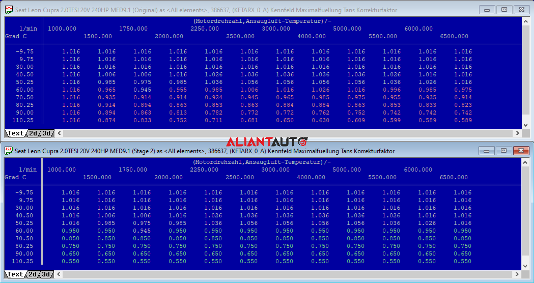
These maps are used to limit (through a correction factor) the maximum desired cylinder filling (rlmx_w) based on engine RPM and intake air temperature. The result of these maps is a factor that is multiplied by the maximum desired cylinder filling from LDRXN (rlmx_w). (KFTARX_0_A, KFTARX_1_A, KFTARX_2_A, KFTARXB_0_A, KFTARXB_1_A, KFTARXB_2_A)
6.2 – KFTARXZK
These maps are used to limit (through a correction factor) the maximum desired cylinder filling (rlmx_w) based on engine RPM and intake air temperature. They are applied in cases of persistent detonation. The result of these maps is a factor that is multiplied by the maximum desired cylinder filling from LDRXN (rlmx_w). (KFTARXZK_0_A, KFTARXZK_1_A, KFTARXZK_2_A)
What should be done?
In this specific Stage 2 setup, the vehicle is equipped with a sufficiently efficient intercooler that maintains intake air temperature within 50°C. A correction factor of 1 is set across the entire RPM range. If the temperature rises above 50°C for any reason, appropriate corrections are applied to reduce the requested cylinder filling (Load). These maps are highly useful for fine-tuning based on intake temperature (Summer – Winter).
KFTARXZK does not need to be modified, as LDRXNZK has been kept sufficiently low.
Note: At high intake temperature values, the maximum requested cylinder filling percentage (Load) is reduced to prevent detonation. Keep in mind that reducing the maximum requested cylinder filling percentage (Load) does not mean that turbocharger pressure will decrease proportionally. The requested turbocharger pressure is designed to increase as intake air temperature rises. This projection is implemented through the FWFTBRTA map, which adds a correction to the ftbr factor.
6.3 – LDORXN
This map is used to limit the maximum desired cylinder filling (rlmx_w) based on engine RPM. It is applied when an issue with turbocharger pressure control is detected.
6.4 – LDORXNHDR
This map limits the maximum desired cylinder filling (rlmx_w) based on the engine speed (RPM). It is used when an issue is detected in controlling the pressure in the fuel rail.
What should be done?
LDORXN and LDORXNHDR should not be modified. In many cases, values equal to or greater than those in LDRXN are recorded in these maps. This is incorrect—do not do this. If there is an issue with pressure and frequent activation of limp mode occurs, the problem should be resolved rather than masked. For large and „unpredictable“ turbochargers, increasing the values in these maps can help prevent real incidents on the road in the event of unexpected pressure problems and sudden load reduction.
7. Boost Pressure Limiter Maps
7.1 – KFLDHBN
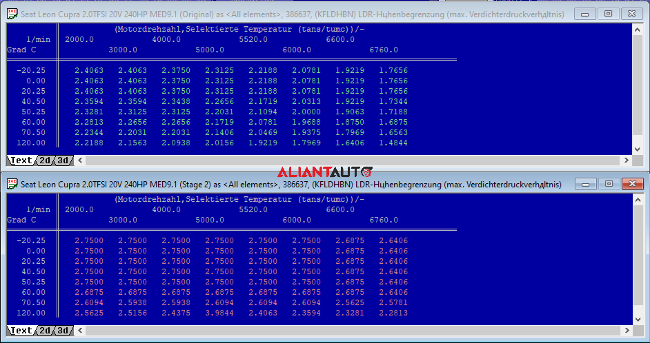
This map determines the maximum permissible turbocharger pressure ratio based on engine RPM and intake air temperature. The purpose is to protect the turbocharger from mechanical overloads. The result of this map is the maximum turbocharger pressure ratio. The obtained ratio is multiplied by the measured atmospheric pressure, resulting in the maximum absolute turbocharger pressure. This absolute maximum pressure is then converted into Load (rlmxko_w) and can be used to limit the maximum cylinder filling (rlmx_w).
7.2 – LDPBN
This map limits the maximum absolute turbocharger pressure based on engine RPM when engine temperature is too high.
7.3 – KLDLUL
This map monitors the maximum deviation between the set and actual turbocharger pressure based on engine speed (RPM). It is used for diagnostics and detecting issues with turbocharger pressure. The result of this map is the maximum deviation between the set and actual pressure, measured in hPa.
7.4 – KFMLDMX
This map monitors the maximum air mass flow measured by the mass airflow sensor (MAF) based on engine RPM and throttle angle. It is used for diagnostics and detecting MAF-related issues. The result of this map is the maximum airflow in kg/h.
What should be done?
The KFLDHBN map is responsible for the maximum absolute turbocharger pressure. Since the goal is to increase pressure under full load, the maximum permissible pressure ratio is increased accordingly. For this specific Stage 2 setup and a power target of approximately 350HP, a relative pressure of around 1.5 bar up to 6000 RPM is required. The values in the LDPBN map are increased to 2550 hPa. There is no need to modify the KLDLUL map. If everything else is correctly adjusted, there should be no deviation between the desired and actual pressure.
Note: After increasing turbocharger pressure, an exceedance of the maximum airflow values (KFMLDMX) may occur. After logging, the actual measured values from the MAF sensor should be compared with those set in this map to determine where adjustments are necessary.
8. Boost Pressure Control Maps
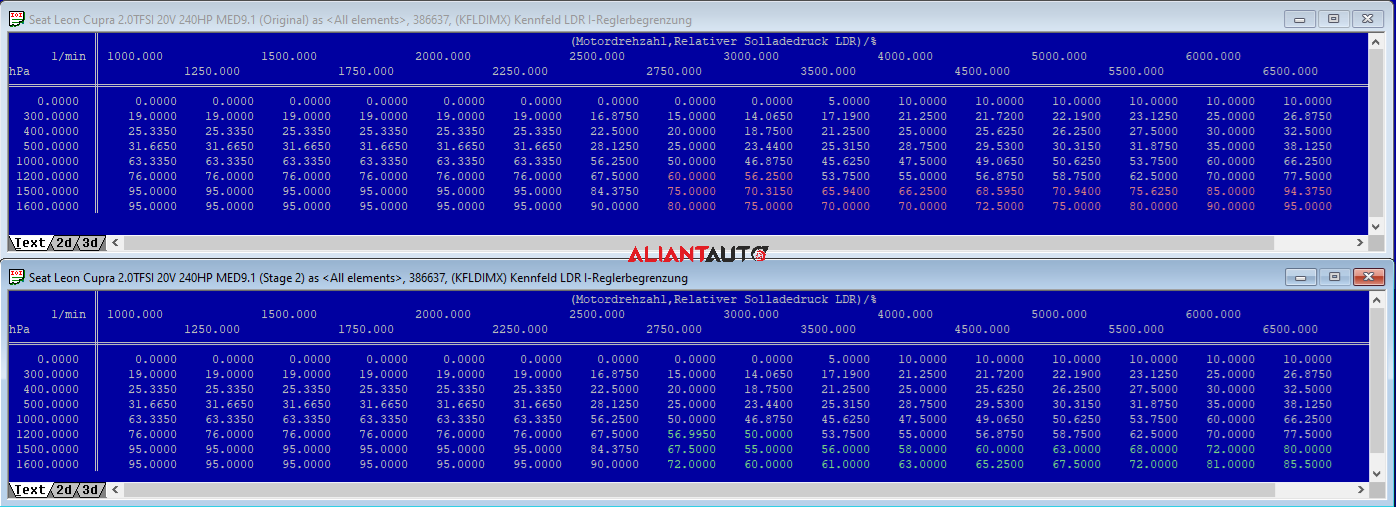
8.1 – KFLDIMX
This is the primary map that defines the limits (integral factor) of the actuator position controlling the turbocharger wastegate based on engine RPM and turbocharger relative pressure. The result of this map is the actuator duty cycle in percentage (%).
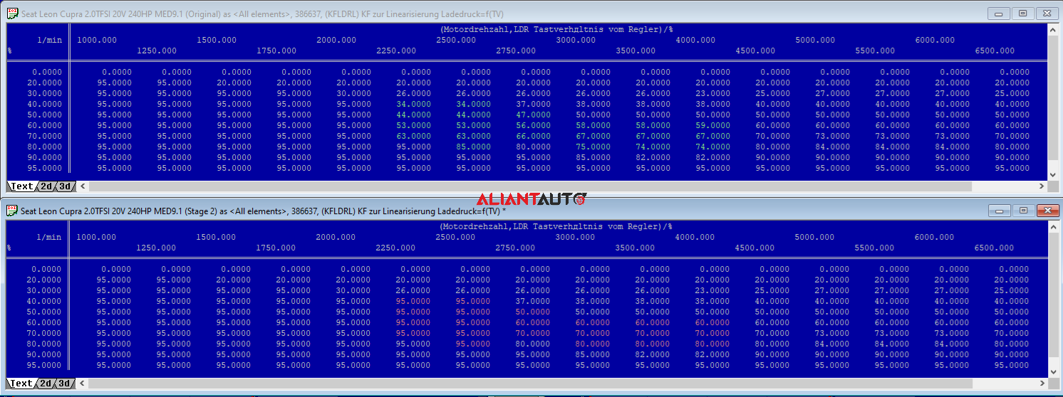
8.2 – KFLDRL
This map is used for linearization and setting the final duty cycle based on engine RPM and the current duty cycle (ldtvr_w). It reflects the specifics of the particular turbo and wastegate.
8.3 – KFLDRQ0 (P)
This map represents the proportional control (P) within the PID control system. Proportional control applies a correction proportional to the difference between the actual and target pressure. This means the target value is never fully reached because, as the error approaches zero, the applied correction also decreases.
- If the actual pressure is too low and the error is large (e.g., during turbo spooling), this map increases the approximate actuator position.
- If the error is small, a smaller correction is applied to maintain pressure close to the target.
Although proportional control (P) works well, it tends to cause fluctuations around the setpoint. To improve performance, two additional factors are introduced: integral and derivative.
8.4 – KFLDRQ1 (I)
This map represents the integral factor (I) of the PID control. The integral factor compensates for imperfections in proportional control by accumulating past errors over time.
- If the pressure remains below the target after proportional control, the integral factor (I) increases the actuator position.
- Instead of stopping at the target, the integral factor (I) continues acting, potentially causing overshooting.
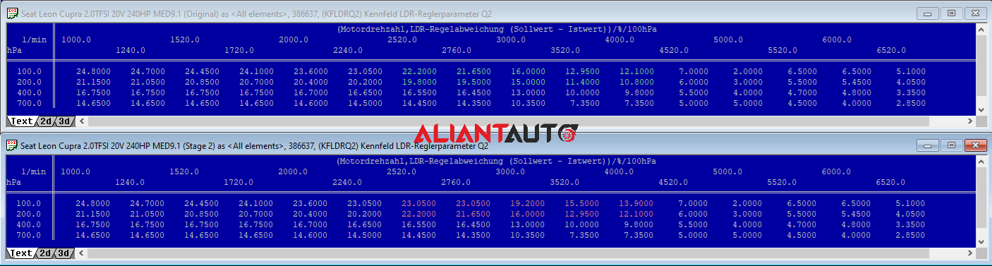
8.5 – KFLDRQ2 (D)
This map represents the derivative factor (D) in the PID control. It minimizes overshooting caused by the integral factor (I) by slowing down the correction as the target pressure is approached.
- Adjust the values in this map to compensate for pressure overshoot when the actual pressure rises quickly.
- Increase the delay (values) if significant overshooting occurs.
- If boost pressure is insufficient, first increase KFLDIMX and, if necessary, reduce KFLDRQ2 values.
8.6 – LDIATA
This map defines correction values for the integral factor (KFLDIMX) as a function of intake air temperature.
What should be done?
Most overboost or underboost issues can be corrected using KFLDIMX and KFLDRQ2. If actual pressure is lower than requested, values in KFLDIMX should be increased in the corresponding RPM range. If actual pressure is higher than requested, values in KFLDIMX should be decreased in the affected RPM range. If an overboost occurs when the turbo spools and reaches the requested pressure, reducing values in KFLDIMX from lower RPMs and increasing values in KFLDRQ2 is recommended.
If adjustments to KFLDIMX and KFLDRQ2 are insufficient, modifications to KFLDRL, KFLDRQ0, and KFLDRQ1 should be considered.
Remember:
- KFLDRQ0 is responsible for rapid control response and alignment of requested and actual pressure.
- KFLDRQ2 eliminates overboost caused by KFLDRQ0.
- KFLDRQ1 ensures stable control.
- LDIATA is modified when different turbocharger control behavior is desired depending on intake air temperature (e.g., Summer, Winter, Highway, Track).
9. Fuel Enrichment Maps
Every gasoline-powered vehicle has what is known as MAIN FUEL CALCULATION. Depending on the amount of air measured by the mass airflow sensor, the computer calculates how long to open the injectors to achieve a stoichiometric mixture, or a ratio of 14.7 units of air to 1 unit of fuel. „Stoichiometric“ refers to the exact ratio of substances in a chemical reaction where no excess of any participating substance remains.
For most of its operation, a gasoline engine runs with a stoichiometric mixture. Enrichment is required when cylinder pressure increases (or under high Load conditions). If the cylinder pressure increases while maintaining a leaner mixture (AFR>= 14.7), combustion stability decreases, leading to detonation (mini-explosions) and high exhaust gas temperatures (EGT). To prevent detonation, the mixture is enriched by adding more fuel, which evaporates and cools the combustion chamber, thereby reducing exhaust gas temperatures.
There are two approaches to mixture enrichment (AFR) under high cylinder filling (Load). If multiple lambda interventions are active at the same time, prioritization is given to the richest mixture or the lowest lambda value.
9.1 Enrichment based on the requested torque set by KFPED (throttle pedal) (LAMFAW).
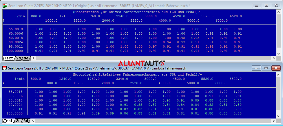
9.1.1 – LAMFA – Determines lambda values as a function of engine RPM and the requested torque from the throttle pedal (KFPED). LAMFA represents values in lambda, where 14.7 AFR equals lambda 1. To clarify, reducing the values in this map decreases the air-fuel ratio below 14.7 AFR, increasing the fuel request and making the mixture richer. Conversely, increasing the values raises the air-fuel ratio above 14.7 AFR, reducing the fuel request and making the mixture leaner. This can put the engine at risk of damage due to higher cylinder temperatures.
9.2 Enrichment for component protection when exceeding a calculated exhaust gas temperature threshold (EGT: Exhaust Gas Temperature) (LAMBTS). The purpose of these maps is to protect engine components such as the cylinder head, exhaust manifold, and turbocharger by enriching the mixture.
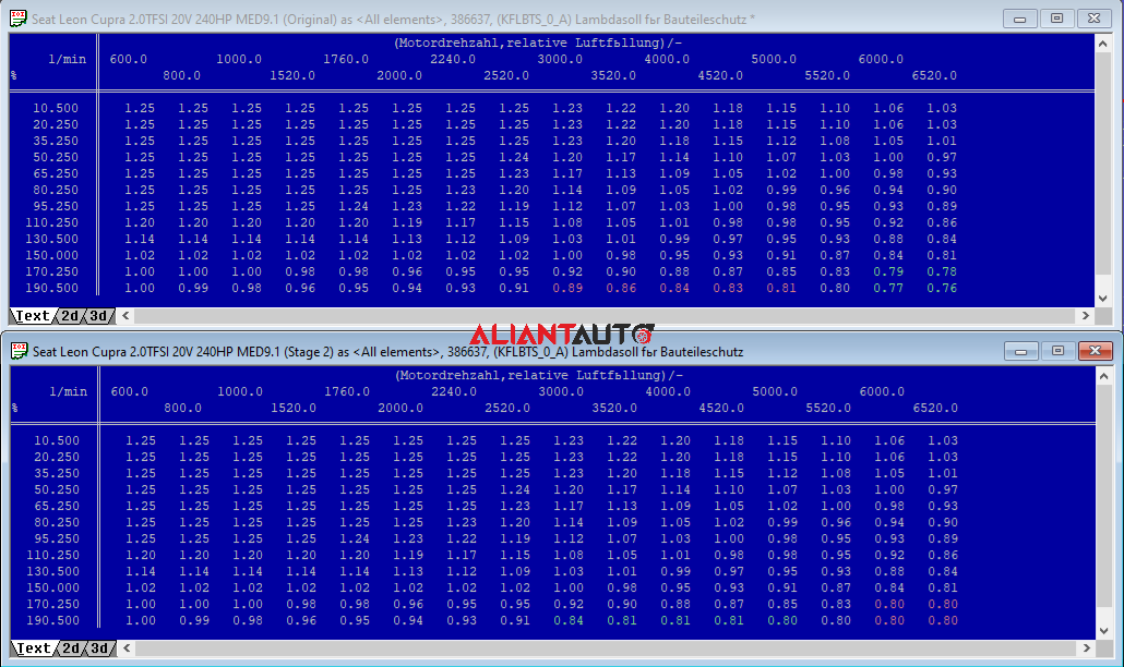
9.2.1 – KFLBTS – This map plays a key role in the enrichment and component protection algorithm and depends on engine speed (nmot_w) and the requested cylinder filling percentage (rl_w) when the swirl flaps are closed. KFLBTS controls enrichment only when the modeled (calculated) temperature exceeds a specified value. KFLBTS displays its values in lambda, where 14.7 AFR corresponds to lambda 1.
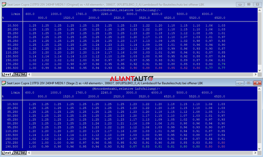
9.2.2 – KFLBTSLBKO – This map plays a key role in the enrichment and component protection algorithm and depends on engine speed (nmot_w) and the requested cylinder filling percentage (rl_w) when the swirl flaps are open. KFLBTSLBKO controls enrichment only when the modeled (calculated) temperature exceeds a specified value. KFLBTSLBKO displays its values in lambda, where 14.7 AFR corresponds to lambda 1.
9.2.3 – KFATMKRH – This map is part of the complex algorithm for predicting the modeled temperature (EGT). The values in this map represent the exhaust gas temperature for lambda = 1 based on engine load and speed. These values serve as reference points for calculating the temperature in the exhaust manifold.
Important: A deterioration in ignition timing efficiency leads to an increase in exhaust gas temperature, but this deterioration can be counteracted with additional mixture enrichment. Therefore, KFLBTS and KFLBTSLBKO do not always set the final target lambda (lambs_w).
The final target lambda also depends on DLBTS, KFFDLBTS, and is expressed by the following formula:
KFLBTS + ( DLBTS * KFFDLBTS ) = lambs_w
KFLBTSLBKO + ( DLBTS * KFFDLBTS ) = lambs_w
9.2.4 – DLBTS – This map serves as an additive factor to the lambda value determined by KFLBTS and KFLBTSLBKO to provide additional enrichment when there is a significant deviation between the actual and the desired ignition angle. DLBTS depends on the delta efficiency of ignition timing (detazwbs). The value of detazwbs tends toward zero if the actual ignition timing (zwist) matches the desired ignition timing (zwbas), or if the retard is close to zero.
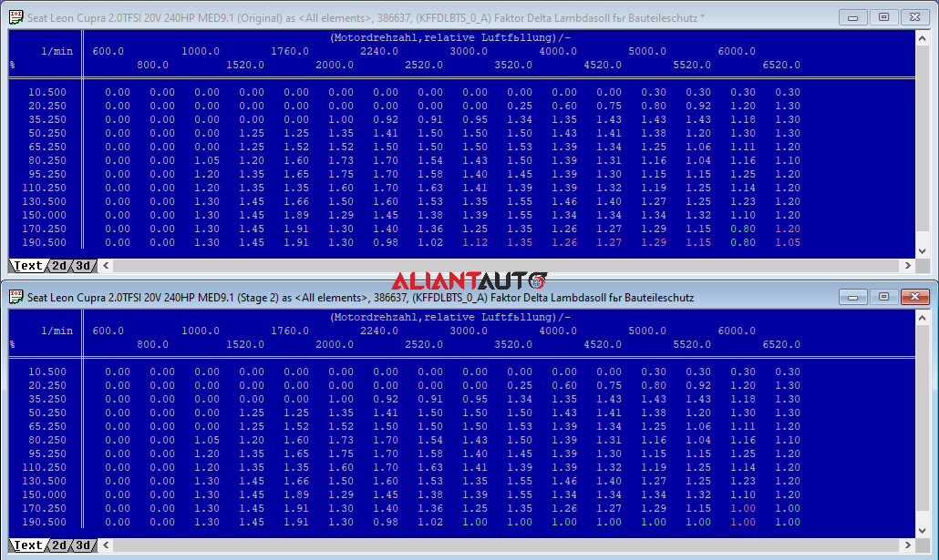
9.2.5 – KFFDLBTS – This map sets a weighting coefficient or a correction factor for the additive value determined by DLBTS. The enrichment from DLBTS can be increased in specific areas, reduced, or eliminated using KFFDLBTS depending on engine speed (nmot_w) and the requested cylinder filling percentage (rl_w).
The enrichment maps for component protection enrich the mixture based on conditions that have already occurred in the engine (elevated exhaust gas temperatures, presence of knock, intake air temperature, etc.). LAMFA is used preventively to respond to the driver’s request before the engine conditions change.
From the factory, LAMFA is deactivated (lambda = 1.00) at low loads and low engine speeds and slightly enriches (lambda = 0.91) at full load and high engine speeds. The idea is to use lambda 1.00 everywhere for emissions and fuel economy while enriching via LAMBTS only when EGT rises.
What should be done?
LAMFA is used for detonation prevention at low actual loads but high requested cylinder filling (Load). BTS is used only when something is really wrong, such as poor fuel quality followed by severe knock and a corresponding rise in temperature to critical levels.
Calibration recommendations:
- LAMFA should be calibrated for optimal AFR when the throttle pedal is pressed beyond 95% across the entire RPM range.
- KFLBTS should be calibrated similarly at high engine speeds and higher cylinder filling percentages.
- The values in the KFFDLBTS map should be changed to 1 at high engine speeds and higher cylinder filling percentages if the safety threshold is reached for any reason (e.g., low-octane fuel). In this case, additional enrichment from DLBTS will occur when there is a corresponding deviation of the actual from the desired ignition timing.

10. Timing Maps
Setting the correct ignition timing is crucial for the operation of a gasoline engine. Ignition that occurs too early or too late often leads to excessive detonation and engine damage. The ignition timing also affects power and average fuel consumption.
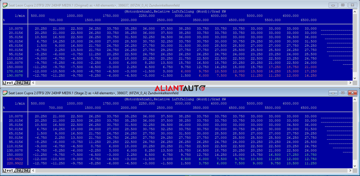
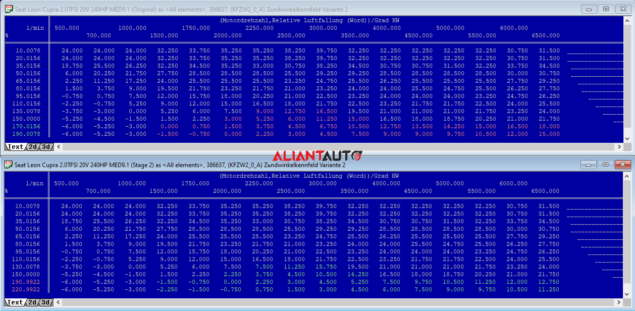
10.1 – KFZW – This map defines the ignition angle based on the cylinder filling percentage (Load) and engine speed (RPM). It is used when the intake camshaft is at minimum advance (high RPM). The result of this map is the ignition timing (in degrees) before top dead center (Grad KW BTDC).
10.2 – KFZW2 – This map defines the ignition angle based on the cylinder filling percentage (Load) and engine speed (RPM). It is used when the intake camshaft is at maximum advance (low RPM). The result of this map is the ignition timing (in degrees) before top dead center (Grad KW BTDC).
The ECU interpolates values from both maps while the intake camshaft is in intermediate positions between minimum and maximum advance.
10.3 – KFZWLB – This map determines the ignition angle based on the cylinder filling percentage (Load) and engine speed (RPM). It is used when the intake camshaft is at minimal advance (high RPM) and the swirl flaps are closed. The result of this map is the ignition timing (in degrees) before top dead center (Grad KW BTDC).
10.4 – KFZWLB2 – This map determines the ignition angle based on the cylinder filling percentage (Load) and engine speed (RPM). It is used when the intake camshaft is at maximum advance (low RPM) and the swirl flaps are closed. The result of this map is the ignition timing (in degrees) before top dead center (Grad KW BTDC).
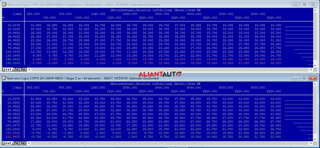
10.5 – KFZWOP, KFZWOP2, KFZWOPL, KFZWOPL2 – These maps define the theoretically optimal ignition angle based on the cylinder filling percentage (Load) and engine speed (RPM). The optimal ignition angle is the angle at which the engine produces the highest torque (if detonation did not exist, which is practically unattainable). These maps are used to measure ignition efficiency and monitor torque output. The result of these maps is the ignition timing (in degrees) before top dead center (Grad KW BTDC).
Ignition efficiency is based on the difference between actual and optimal ignition angles. For example, if KFZW is equal to or greater than KFZWOP, then ignition efficiency is 100%. KFZWOP maps do not affect the actual ignition angle directly. Instead, they have an indirect effect on mixture enrichment when the difference between KFZWOP and KFZW is significant. When ethanol (E85) is used, KFZWOP should have higher values (since ethanol has a theoretically higher optimal ignition angle due to its slower combustion and greater resistance to detonation).
What should be done?
When the cylinder filling percentage (Load) is increased by raising the boost pressure from the turbocharger, it may be necessary to reduce ignition timing at peak load to prevent excessive detonation and automatic ignition retardation. To begin searching for the maximum ignition angle, the timing advance must first be restored to reasonable limits (safe ignition angle) before adjusting the desired turbocharger pressure and air-fuel ratio. Then, an incremental increase of 2 degrees is applied while logging data. If no automatic ignition retardation (knock retard) is observed across all cylinders, another 2-degree increase is applied and logged again. If automatic ignition retardation greater than 3 degrees is observed across all cylinders, the last increase is reversed, and the previous setting is used.
For ethanol tuning, the same approach is taken, but instead of logging, actual torque and power are measured on a dynamometer. When no further increase in torque or power is observed after another ignition timing increment, the last increase is reversed.
Note: When adjusting ignition timing, the step size for standard ignition retardation or the number of engine cycles required to reduce retardation after detonation stops being detected can be reduced. Knock sensor sensitivity calibration can also be altered. The goal is to achieve additional power gains, but this comes with inherent engine risks!
It is strongly recommended that standard knock control not be manipulated, or if adjusted, only minimal deviations should be applied with great caution. A better approach to achieving more timing advance is through race fuel, compression reduction, water-methanol injection, etc.
For Stage 1 tuning, KFZWOP is not modified, but linear extrapolation can be performed if a higher Load value than the maximum defined one is set.

11. Fuel Pressure Maps
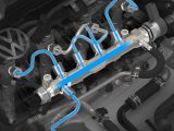
MED9 engine control units, which manage TFSI engines, have been developed based on the ME7 units that control 1.8T engines. The main difference in TFSI (GDI) is the direct injection of fuel into each combustion chamber at a pressure of up to 110 bar, in contrast to 1.8T, where the injectors are positioned on the intake manifold, injecting fuel at a pressure of 3-4 bar onto the back of the intake valves. To achieve such high pressure (up to 110 bar), in addition to the familiar LPFP pump in the fuel tank, another pump, HPFP, has been added in the engine compartment.
11.1 – HPFP – High-pressure fuel pumps are mechanical and are usually driven by the camshaft. A cam lobe on the camshaft presses on a „follower“ or „lifter“ (cam follower), which moves the pump piston. The piston has two cycles: suction and compression. The solenoid on the side of the pump controls how much fuel is compressed. At low engine load, the solenoid remains open longer, compressing a smaller fuel volume. At high engine load, the solenoid closes earlier, compressing a larger fuel volume. The duration for which the solenoid remains open determines how much fuel reaches the fuel injectors.
The original high-pressure pump is unable to provide the required fuel pressure when the turbocharger pressure exceeds 1.3 – 1.4 bar at medium RPM. The pump supplies fuel 1.5 times per engine revolution or a total of 3 times per camshaft revolution. Following this logic, the pressure of the original pump will not be an issue at high RPM (above 5500 RPM), but at 2500 – 4500 RPM and high load, the original pump will not be sufficient.
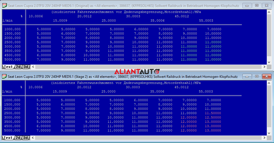
11.1.1 – KFPRSOLHKS – Sets the fuel rail pressure value during homogeneous operation and active knock protection.
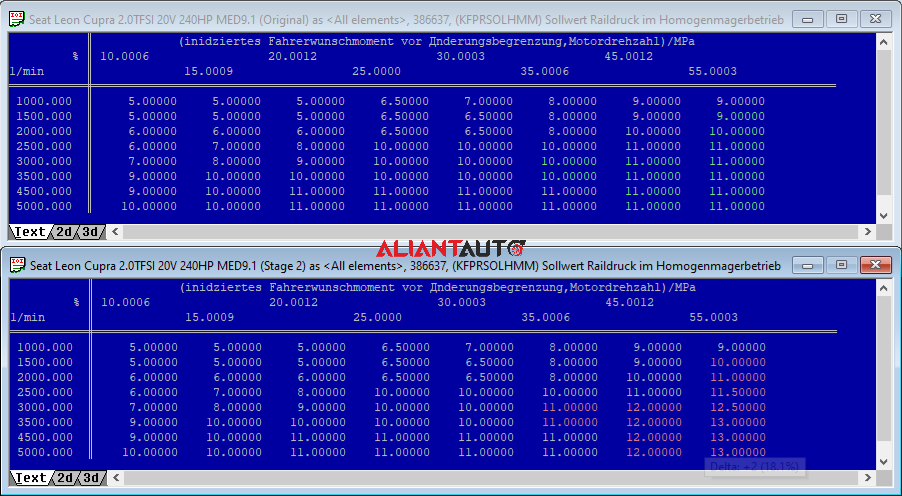
11.1.2 – KFPRSOLHMM – Sets the fuel rail pressure value during homogeneous operation and lean mixture.
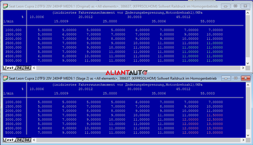
11.1.3 – KFPRSOLHOM – Sets the fuel rail pressure value during homogeneous operation.
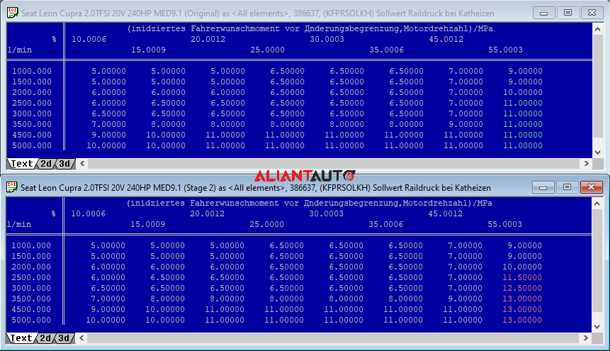
11.1.4 – KFPRSOLKH – Sets the fuel rail pressure value during catalyst heating.
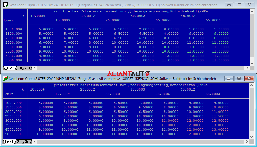
11.1.5 – KFPRSOLSCH – Sets the fuel rail pressure value during switching operations.
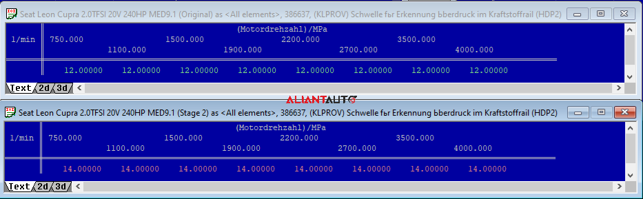
11.1.6 – KLPROV – Sets the threshold for detecting excessive fuel rail pressure.
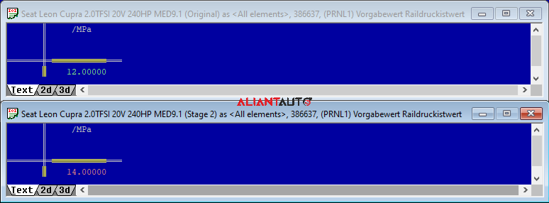
11.1.7 – PRNL1 – Sets the threshold for detecting excessive fuel rail pressure.
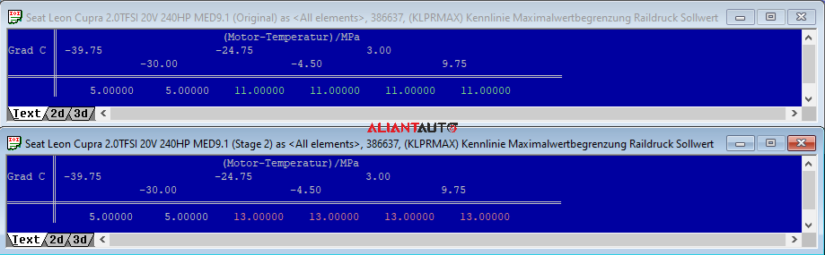
11.1.8 – KLPRMAX – Sets the maximum fuel rail pressure value according to engine temperature.
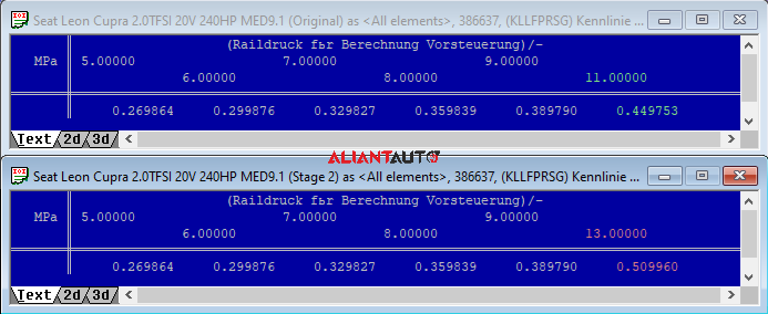
11.1.9 – KLLFPRSG – Sets the efficiency of the high-pressure pump.
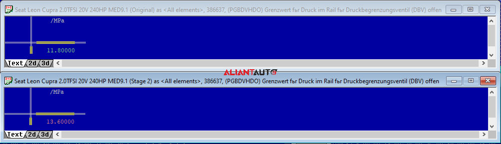
11.1.10 – PGBDVHDO – Sets the threshold fuel rail pressure at which the pressure control valve opens.
What should be done?
For this specific Stage 2 and power of approximately 350 HP, a maximum cylinder filling of about 220% (Load) or a relative turbocharger pressure of about 1.5 bar up to 6000 RPM will be required. To reduce injector times at this cylinder filling, higher rail pressure will be necessary. The fuel rail pressure values in the aforementioned maps are increased up to 135 bar.
Attention! Do not exceed 8ms injector time, with 10ms being the absolute maximum. Additionally, if the standard PRV has not been replaced with an RS4 PRV or another aftermarket valve, fuel pressure cannot exceed 118 bar. The standard PRV opens at 118 bar, while the RS4 valve opens at around 136 bar.
To achieve higher and more stable pressure at Stage 2, a common modification is using a larger pump piston. When replacing the pump piston, adjustments to the following maps are necessary:
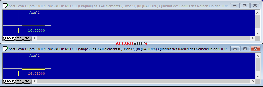
11.1.11 – RQUAHDPK – Sets the squared radius of the high-pressure pump piston.
It is calculated using the formula: RQUAHDPK = (Diameter / 2) ^ 2
The original piston diameter for 2.0 TFSI is 8mm. RQUAHDPK = (8 / 2) ^ 2 = 16.00
The piston diameter for ARP upgrade is 9.5 mm. RQUAHDPK = (9.5 / 2) ^ 2 = 22.5625
The piston diameter for Autotech/KMD/VIS Motorsport upgrade is 9.8 mm. RQUAHDPK = (9.8 / 2) ^ 2 = 24.01
What should be done?
This value is changed only when the piston diameter is modified, such as installing a larger piston or a new pump with a larger piston.
11.1.12 – SKHDPMX – Sets the stroke of the high-pressure pump piston. The piston stroke depends on the size of the intake camshaft lobe.
The piston stroke in the first (A and B series) 2.0 TFSI is 5mm.
The piston stroke in CDLs 2.0 TFSI is 5.4mm.
The piston stroke in 2.5 TFSI is 4.5mm.
What should be done?
This value is changed only when the piston stroke is modified, such as installing a camshaft from a CDLs engine in an A and B series engine.
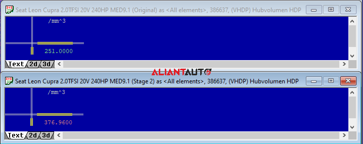
11.1.13 – VHDP – Sets the volume of the high-pressure pump.
It is calculated using the formula: VHDP = RQUAHDPK * pi * SKHDPMX
What should be done?
This value is changed only when the piston diameter and/or stroke are modified.
Note: At Stage 1, no change in the original pump pressure is necessary. The actual pump values should be monitored when setting turbocharger pressure. If the actual pump pressure starts deviating from the set value (drops below 110 bar), the turbocharger pressure should be adjusted accordingly.
11.2 – LPFP – The fuel pump in the tank in GDI systems is more responsible for volume than pressure. The fuel from this side of the system is referred to as the low-pressure side.
What should be done?
For this specific Stage 2 and power of approximately 350 HP, replacing the original LPFP pump is NOT necessary, but the fuel inlet to the HPFP pump must be drilled out to prevent pressure drop. The original inlet is about 1.2 mm and should be drilled to 5 mm. This way, the LPFP pump in the tank will operate „easier,“ and the pressure will not drop at high RPM! It is important to maintain relatively stable low pressure because HPFP is designed to work with static (stable) pressure. If the actual low pressure starts dropping and deviating from the set value, this may result in an increase in actual high pressure (HPFP creep).
At Stage 3, the pump must be replaced with a larger one (higher flow rate – TTRS/RS3) and possibly the pump controller. When using a non-original pump at Stage 3, adjustments to the following maps are necessary:
11.2.1 – KFNTBKS – Sets the target pressure value as a function of fuel temperature and engine RPM.
11.2.2 – KFFLAF – Sets the pump duty cycle based on fuel flow to the injectors (g/min) and pressure (kPa) specified by KFNTBKS. When replacing with a TTRS/RS3 pump and original controller, the pump duty cycle must be reduced to prevent overheating under high load.
11.2.3 – LEPWMMX – Sets the maximum pump duty cycle to 92%.
12. Fuel Trims Correction Maps
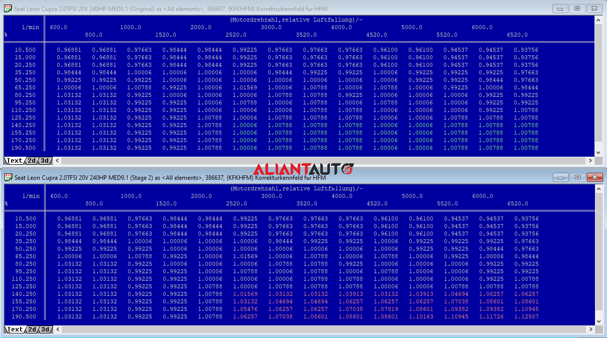
12.1 – The KFKHFM map is used for indirect correction of injector timing due to the non-linearity of the intake system (Intake, MAF).
What should be done?
If the standard mass airflow sensor (MAF) and intake system are used, this map should not be modified. Changes may be required when a non-standard MAF sensor, a modified MAF housing, or an altered intake system is installed. Adjustments should be made based on real-time Lambda control logs at various throttle positions, RPMs, inclines, and speeds to determine which region of the map requires correction. If KFKHFM is properly calibrated, significant deviations in STFT and LTFT should not be observed.Note: When the intake tract diameter is increased, the values recorded by the MAF sensor decrease. Lower MAF readings artificially reduce the actual cylinder filling percentage (Load), which incorrectly increases the ignition timing according to the KFZW map (Load/RPM). This is confirmed by positive fuel corrections since fuel volume calculations are based on the same readings.
If the actual cylinder filling percentage follows the target values, corrections should be applied to FKKVS.
12.2 – The FKKVS map is used for injector timing correction due to the non-linearity of the fuel system (fuel rail).
What should be done?
If standard injectors are used, this map should not be modified. Adjustments may be required when non-standard injectors are installed (even if the primary constant is correctly set). Corrections should be made based on real-time Lambda control logs at various throttle positions, RPMs, inclines, and speeds to determine where injector timing requires adjustment. If FKKVS is properly calibrated, significant deviations in STFT and LTFT should not be observed.
13. DSG
For vehicles equipped with a DSG (DQ250) automatic transmission, the torque limit in the DSG control unit must be adjusted. The default limit is typically around 350Nm to 380Nm, depending on the specific application. It is not advisable to transmit unrealistic torque values to the transmission. Additionally, the engine ECU must be configured to send a higher torque value to the transmission ECU (MDNORM, MDMAXKBI, KFMIRL, KFMIOP) after its limit has been increased. Failure to do either will result in continuous clutch slippage. The DSG system limits the maximum clutch solenoid current based on the torque value provided by the ECU. Depending on the DSG version, there is usually sufficient reserve pressure available—approximately 15-16 bar.